March 2008 "3072RT / 3772RT / 3772RT HD" Service & Parts Manual - ANSI Specifications
Page 2-10
Outrigger Stowed
Switch
Outrigger
Pressure
Switch
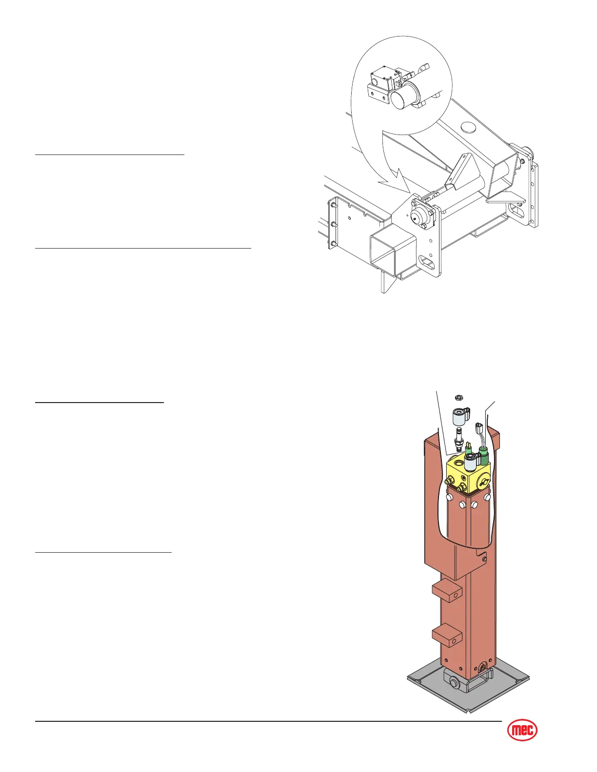
LIMIT SWITCH
The Limit Switch indicates Platform Height above
approximately 10 feet (3m). The switch operates in
conjunction with the circuit board located in the lower
control box and the proportional circuit board located
in the upper control box.
Lower Controls Circuit Board
When the platform is elevated above 10 feet (3m) the
limit switch is activated, causing the circuit board to;
• enable tilt sensor cutout operation
• lockout outrigger operation.
Upper Controls Proportional Circuit Board
When the platform is elevated above 10 feet (3m) the
limit switch is activated, causing the proportional
circuit board to;
• enable elevated drive speed.
OPTIONAL OUTRIGGERS SWITCHES
If the machine is equipped with outriggers, each of the four (4)
outriggers has a Stowed Switch and a Pressure Switch.
Outrigger Stowed Switch
• Indicates full retraction of the outrigger cylinder.
• Drive Function: The machine will drive when the Outrigger
Stowed Switch on all four (4) outriggers is engaged. If one (1)
or more Outrigger Stowed Switch is open (not engaged) the
machine
will not drive
.
• Lift Function: If one (1) or more Outrigger Stowed Switch is
open (not engaged) the machine
will not lift
unless all four (4)
outriggers are fully deployed.
Outrigger Pressure Switch
• Indicates full deployment of the outrigger.
• Lift Function: When deployment begins the Outrigger
Stowed Switches open and lift function is disabled. When all
four (4) outriggers reach full deployment the Outrigger Pres-
sure Switches close (engage) and lift function is restored.