"3072RT / 3772RT / 3772RT HD" Service & Parts Manual - ANSI Specifications March 2008
Page 2-11
CONTINUITY CHECKS
Check Toggle Switch:
• Disconnect wires and connect one probe of ohm meter to the connection on toggle switch
and other probe on other connection.
• When toggle is open, there should be no reading, and when closed there should be a low
reading.
Check Selector Switch
• Disconnect wires and connect one probe to common of switch and the other to normally
open terminal.
• With the switch flipped, there should be a low resistance.
Check Emergency Stop Button
• Disconnect wires and connect one probe of ohm meter to connection on button and other
probe on other connection.
• There should be no reading with the button pressed and a low resistance with it reset.
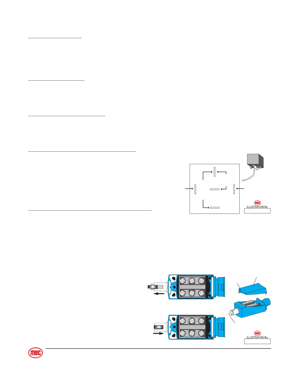
Check Relay Operation (refer to illustration)
• With the #85 terminal grounded, apply voltage to
#86 terminal connection.
• Confirm normally closed (#87A) contacts are
opening. Continuity with #30 will be broken.
• Confirm normally open (#87) contacts are closing.
Continuity with #30 will be made.
Check Limit Switch Operation (refer to illustration)
• Loosen cover screw and lift cover from switch.
• Mark and disconnect wires.
• With one probe of ohm meter to “A” and other probe to “B”, release the plunger.
- Low resistance should be seen. Same result should be seen between “C” and “D”.
• With one probe of ohm meter to “A” and other probe to “B”, depress the plunger.
- High resistance should be seen. Same result should be seen between “C” and “D”.
• “E” and “F” should
show opposite results
as seen on previous
tests though there may
not be any circuits on
these terminals.
ART_2330
RELAY DETAIL
(relay energized)
85 86
87
87A
30
OPEN
CLOSED
B+B−
ART_2331
A
B
C
D
E
F
A
B
C
D
E
F
A - B CLOSED
C - D CLOSED
E - F OPEN
A - B OPEN
C - D OPEN
E - F CLOSED
SWITCH RELEASED
SWITCH DEPRESSED
NO
NC
NC
NO
NC
NC
Cover
Plunger
Cover
Screw