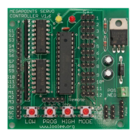
MegaPoints servo controller Revision 24 April 2016
www.loolee.org Page: 15
Appendix
Summary of menu commands
These are features accessed by holding a button or combination as power is applied to
the board.
These functions are accessed by pressing a button during normal use.
Feature available while in programming mode.
Slave enable
Turns the unit into a slave controller. Can now be connected to a
master unit and will only accept commands from the master. Local
switch reading is now disabled. The YELLOW and RED LEDs will flash
alternately for 3 seconds to indicate slave mode is set. Subsequent
power on of the board will also result in the YELLOW and RED LEDs
flashing to remind you the board is slaved.
Slave enable & set slave address
As above (Slave enable) plus reads switches S1-S4 to set slave address.
Master enable
Disable slave controller mode.
Factory reset – perform prior to installation!
Perform an installation reset. RED LED flashes for about 5 seconds
during the reset. After resetting, all end points and servo directions are
reset back to the factory condition (centre). Slave controller mode is
disabled. As the end points of all servos have been reduced to 0, no
servos will move until the end points have been individually
programmed. This feature ensures all servos are correctly centred
ready for installation and prevents the servo from over driving and
stalling.
LAB reset
Perform a LAB factory reset. As above (Factory Reset) but with
endpoints for each servo. Only to be used for software testing and
development. Do not use when installing on a layout as servos may be
overdriven and stalled.
Operate the points corresponding to switch number.
Servo speed (points mode)
Select memory button 1 – 3. M1 sets the servo speed to slow, M2 to
normal and M3 to fast operation.
Memory recall
Select memory 1 – 3. The RED LED will illuminate to indicate a memory
is currently in use.
Disables memory mode and resumes reading the switches S1 – S12.
Program memory
Long press (more than 2 seconds) programs the memory for the button
pressed. The unit will memorise the points as they are currently set.
Programming mode
Enter servo programming mode. The RED LED illuminates in