www.megger.comDLRO100E, 100X & 100H – 100A
9
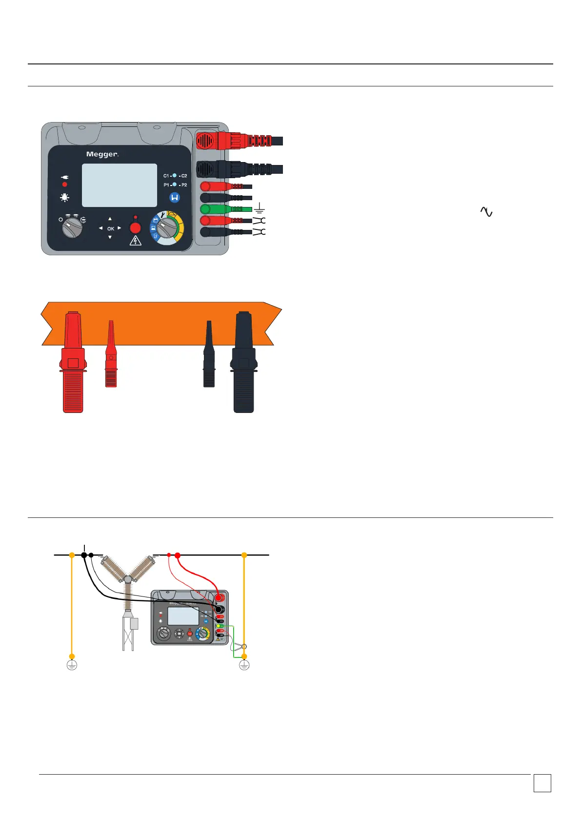
Lead connections
C1
P1 P2
C2
MAN
AUTO
100A
50A
10A
Ω
DLRO100
TEST
OK
P1
P2
C1 - - C2
P1 - - P2
Leads connected to the instrument with the Kelvin arrangement
below showing correct positioning of Current (C1,C2) and
Potential probes (P1,P2).
The earth terminal g is used to detect floating voltage on
the test subject relative to the C2 (0 V) terminal. High floating
voltage on the test subject could present a hazard to the user
and the DLRO. If the test subject is ±200 mV from the C2 (0 V)
terminal, test will be inhibited. The noise symbol will show
when the test is inhibited. Disconnect from the earth terminal
when this feature is not in use.
Section of test piece under test.
The current terminals (C1 and C2) must be connected outside of
the potential terminals (P1 and P2), to ensure accurate readings.
DualGround™ and DC Clamp connection
Test Leads
As an additional safety precaution, perform the test with both
ends of the test object grounded.
Connect the DC clamp to one of the ground connections. The
DC clamp measures current flowing through the ground loop
and the DLRO100 compensates for this current loss automatically
resulting in a more reliable reading.
Refer to the MCPD100L manual for how to use the DC current
clamp.
Connect the earth connector to a suitable earth. Do not leave
the earth connection un-terminated or floating.
C1
C2
P2
P1
C2 (0V)