Basic Operation and Installation
Rev 3.4
Mellanox Technologies
22
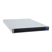
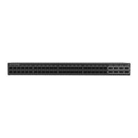
Figure 10: Port Numbering
3.4.1.2 Top and Bottom Orientation
Figure 11: Top and Bottom Ports
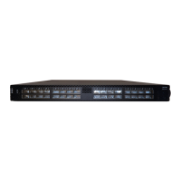
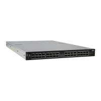
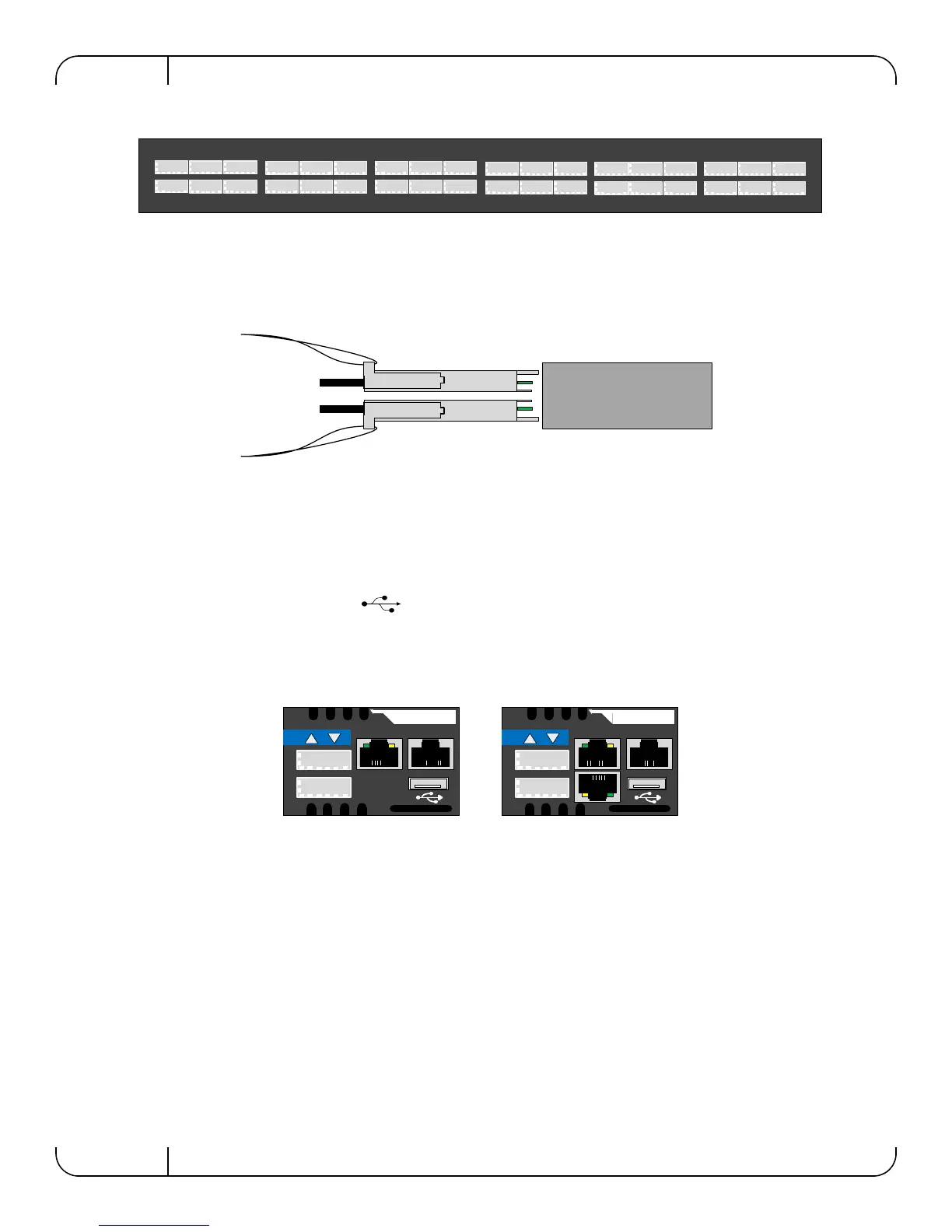
3.4.2 Management and FW updating Interfaces
There are three interfaces to connect to the IS50XX. They are:
• 1 or 2 connectors labelled “MGT”. Use these connectors to connect to the Ethernet. The
IS5035 switch has two MGT connectors whereas the IS5030 has one.
• 1 USB port that is labelled . This interface can be used to update software or firm-
ware.
• 1 connector that is labelled “CONSOLE”. Use this connector to connect to the host PC.
Figure 12: Management Interfaces
3.4.2.1 RJ-45 Connector (CONSOLE) Internally Managed Switches only
The port labelled “CONSOLE” is for a local host connection to the management module. This is
used the first time the switch is connected. An HAR 000028 harness is included in the package to
connect to a DB9 connection on a host PC. Connecting to a local host PC and following the
instructions in the Installation Guide, “Configuring the Switch for the First Time”, must be done
before any remote management is available. For the Socket pinout see
“RJ45 CONSOLE Inter-
face” on page 74.
This connector is not found in unmanaged (externally managed) switches.
1
2
3
4
5
6
7
8
9
10
11
12
13
14
15
16
17
18
19
20
21
22
23
24
25
26
27
28
29
30
31
32
33
34
35
36
MGT
IS5035
CONSOLE
MGT
IS5030
CONSOLE
Internally Managed
with chassis manager
Internally Managed
with FabricIT manager
 Loading...