42 | Page
LP GAS PRESSURE REQUIREMENTS
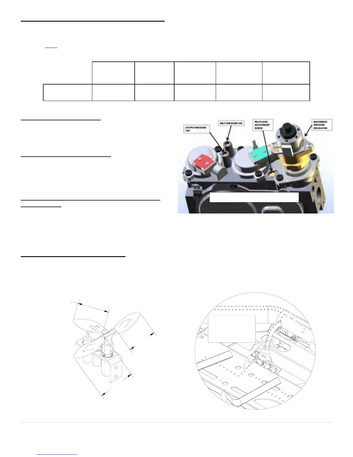
Inlet and manifold gas pressure checking taps are located on gas valve. These ports are only accessible from the outer
left side of the fireplace. A qualified installer shall take pressure measurements at these ports to verify and set the correct
gas pressures during the LP Kit installation and before facia materials are installed over the front of this fireplace. Manifold
pressure must
EHWDNHQDWWKH³0$1,)2/'35(6685(WDSDQGLQOHWSUHVVXUHDWWKH,1/(735(6685(WDSwith the
burner operating by a qualified installer.
DESIRED
INLET
PRESSURE
MINIMUM
INLET
PRESSURE
MAXIMUM
INLET
PRESSURE
AIR SHUTTER
POSITION
L.P. GAS 11.0" W.C.
(2.75 kPa)
11" W.C.
(2.75 kPa)
13.0" W.C.
(3.24 kPa)
1/4" OPEN MIN.
(5 mm)
REGULATE THE FLAME HEIGHT TO "HIGH" POSITION. OUTLET GAS PRESSURES MAY VARY PLUS OR MINUS 5%.
LPG PROPER INPUT RATES:
With the proper orifices installed, as specified above, this
fireplace utilizing LP Gas will have a maximum input rate of
40,000 Btu/Hr.
LEAK TESTING REQUIREMENTS
Prior to completing the conversion process, check for gas
leaks with soap and water solution at all plumbing joints
prior to placing this appliance into operation. It is recom-
mended that all gas-plumbing joints, factory installed and
field installed are checked for leaks.
PILOT FLAME AND MAIN BURNER RELATIONSHIP
VERIFICATION
Prior to completing the conversion process, the qualified
service technician must, light the pilot light and verify the relationship between the pilot light flames and the main burners.
The pilot light flames directed towards the propagation ports on the rear and front burner must overlap the propagation
SRUWVRQWKHEXUQHUV7KHSLORWOLJKWIODPHVPXVWEHDPLQLPXPRIô´ORQJDQGPXVWRYHUODSWKHSURSDJDWLRQSRUWVRQERWK
the rear and front burners as shown in the diagram, below. Verify that the burner tubes ignite quickly and the burner
flames propagate smoothly along the entire length of the burners.
PILOT FLAME LENGTH ADJUSTMENT
If the pilot light flame length is too short and the system does not maintain a standing pilot, a qualified installer may
increase the length of the pilot light flames to meet the two requirements: Minimum pilot light length to maintain a
standing pilot light and the pilot light flames must be long enough to overlap the front and rear burner ports.
Figure 23: Pressure Test Port
1" MIN.
1" MIN.
1" MIN.
Pilot Flame
must overlap
Burner Ports