85-03-01120 M27 Page 93
6.4 OVER FIRING OR UNDER FIRING OF BURNER
NEVER "over fire" or “under-fire” units by increasing or decreasing the main orifice sizes or by adjusting gas pressure to increase
BTUH above nameplate specifications.
Over firing can cause permanent damage to firebox and deterioration of parts and void the warranty.
Under-firing can potentially cause delayed ignition and lead to property loss and person injury and will void the warranty.
If you are using a “backyard” Natural Gas well as the gas source, you must submit formal gas analysis data
sheets to Mendota Fireplaces for review and calculation of proper main burner orifice sizes prior to first
firing. It is known that unpurified Natural Gas from “backyard” wells can contain high energy levels causing
over firing. Further, unpurified gas can contain high levels of Sulphur and other compounds which can
damage the burner materials and the ceramic glass. Use of unpurified gas will void the warranty for this
product.
6.5 PILOT OUTAGE AND RE-LIGHTING
If pilot goes out, be sure to wait a minimum of five minutes before attempting to re -light. If lockout occurs
frequently, contact you Mendota Dealer for diagnosing the problem.
Frequent pilot outages can be caused by many factors and must be properly diagnosed, and the primary cause identified. It
should never be assumed that the ignition control system is faulty without proper diagnosis.
6.6 COMBUSTION SYSTEM MILLIVOLT READINGS
Millivolt readings must be taken by a qualified installer at the time of installation and after any interruption in burner operation.
These readings will establish proper thermopile millivolt generation and assure trouble-free burner operation. Readings must be
taken with:
A. Pilot ONLY operating.
B. Main Burner operating.
PILOT ONLY OPERATING
Thermostat "OFF” Minimum Millivolts 325
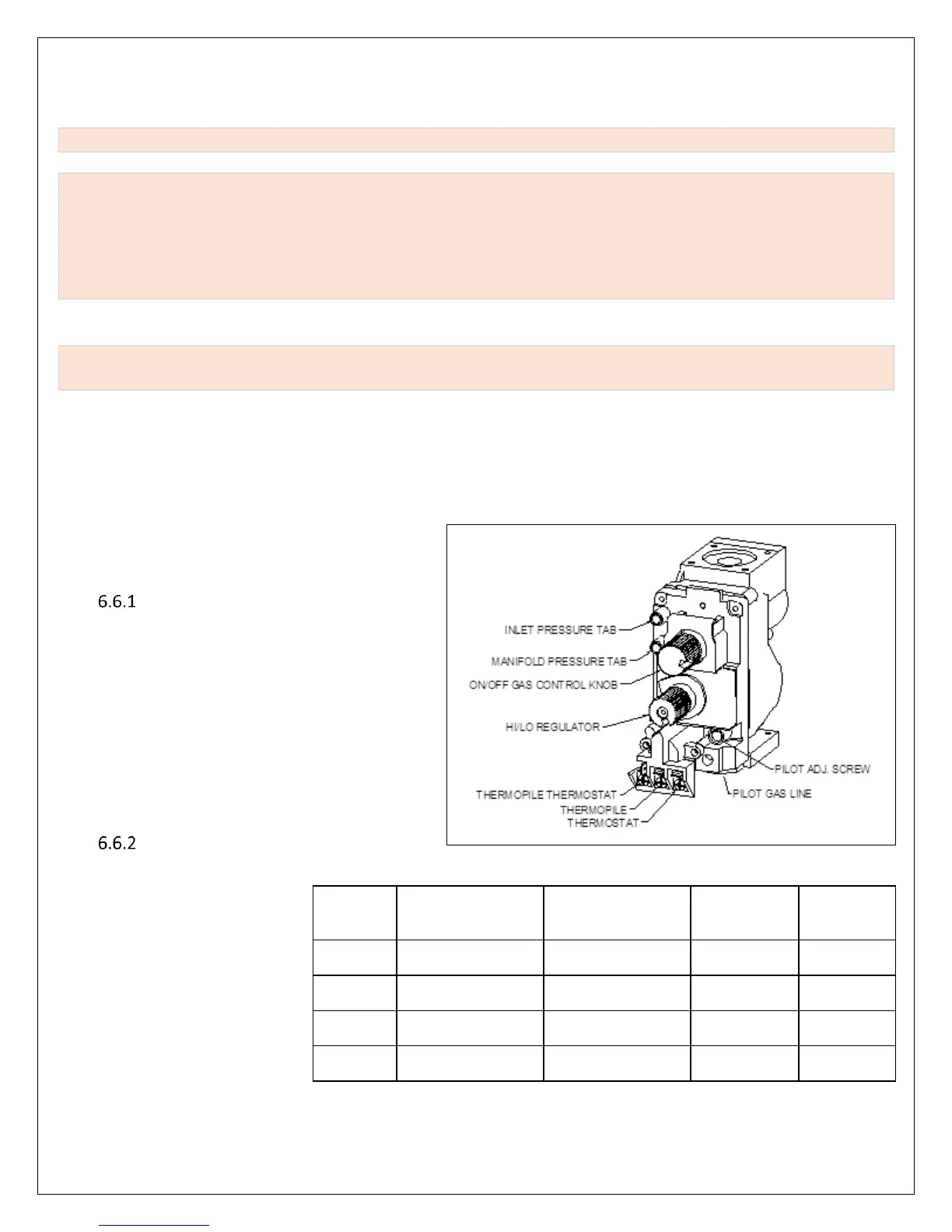
Using a Millivolt Meter, a millivolt reading should be
taken by attaching Meter leads to terminals #1 and #2 on
the main gas valve. The Meter must read a minimum of
325 millivolts with the Pilot Light operating, Thermo-stat
turned "OFF" and Main Burner "OFF". To increase or
decrease millivolts (and pilot flame) adjust pilot screw on
control (see Error! Reference source not found.). Pilot
Flame must be a minimum of ¾” long on all three
branches.
MAIN BURNER OPERATING
Thermostat "ON" -Minimum Millivolts 100
Using a Millivolt Meter, a millivolt reading
should be taken by attaching Meter leads to
terminals #2 and #3 on the millivolt panel on
the main gas valve. The Meter must read a
minimum of 100 millivolts with the Gas Cock
Dial turned “ON”, Thermostat "ON" and Main
Burner operating. To increase or decrease
millivolts (and pilot flame) adjust pilot
screw on control