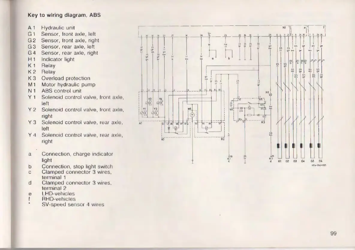
Key to wiring diagram , ABS
A1 Hydraulic unit
G1
Sensor, front axle, left
G2
Sensor, front axle, right
G3
Sensor, rear axle, left
G4 Sensor, rear axle, right
H 1 Indicator light
K1
Relay
K2 Relay
K3 Overload protec tion
M 1 Motor hydraul ic pump
N 1 ABS contro l unit
y 1
Solenoid control valve, front axle.
left
Y2 Solenoid control valve , front axle,
right
Y3 Solenoid cont rol valve, rear axlo.
left
Y4 Solenoid control valve, rear axle,
right
a
Connection , charge indicator
light
b
Connection, stop light switch
C Clamped connector 3 wires,
N!i4-0U,2-825
terminal 1
d Clamped connector 3 wires ,
term inal 2
e LHD-vehi cles
I RHO-vehi cles
SV-speed sensor 4 wires
99