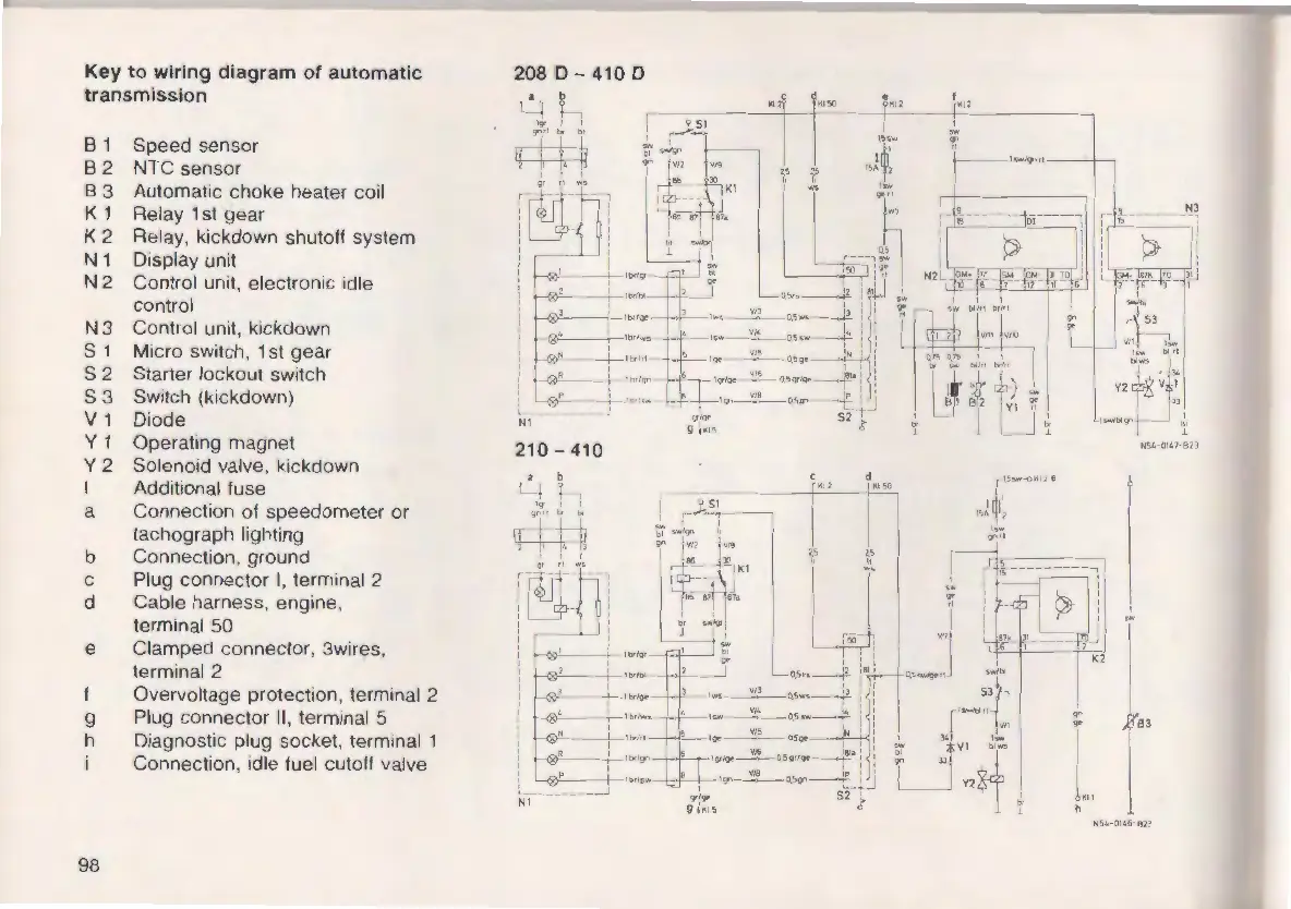
Key to wiring diagram of automatic
transmission
B 1 Speed sensor
B 2 NTC sensor
B 3 Automatic choke heater coil
K 1 Relay 1st gear
K 2 Relay, kickdown shutoff system
N 1 Display unit
N 2 Control unit, electronic idle
contro l
N 3 Control unit, kickdown
S
1 Micro switch, 1st gear
S 2 Starter lockout switch
S 3 Switch (kickdown)
V 1 Diode
Y 1 Operating magnet
Y 2 Solenoid valve, kickdown
I Additional fuse
a Connection of speedometer or
tachograph lighting
b Connection, ground
c Plug connector I, terminal 2
d Cable harness, engine ,
terminal 50
e Clamped connector, 3wires,
terminal 2
t Overvoltage protection, terminal 2
g Plug connector II, terminal 5
h Diagnostic plug socket, terminal 1
Connection , idle fuel cutoff valve
98
208 0 - 410 D
• b
LI h
q--~~
1 ' '
:@!:~
,~J,
NI
~--t-ltltlbf
'
-.
~
,--.,t,,, ....
--,.-.1tir1,1 -
~
1-'orkT1
'
- 1 .. lt.'1<; ,..
210 - 410
..
feJ
~
1~,
1
h
N!.4-01'6-Bn