Description Nm lb‑in. lb‑ft
Starter motor cable nuts (2) 4.0 35.4 –
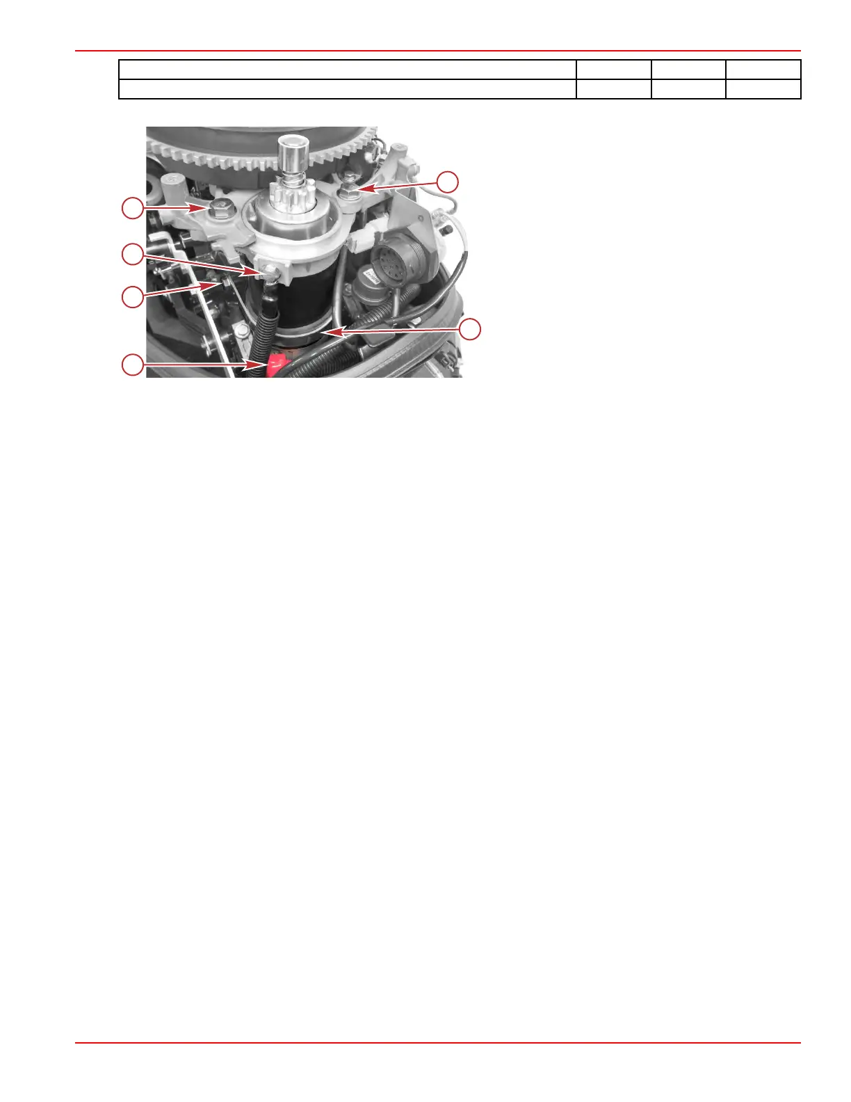
7. Cover the positive electrical connection with the red rubber boot.
Some items shown removed for clarity
a - Positive cable with rubber boot covering the
connection
b - Isolator bracket screw (2)
NOTE: The port side isolator bracket screw
is not shown in this view.
c - Negative cable connection point
d - Starter motor mounting screws (2)
e - Starter motor isolator bracket, positioned around
rubber isolator
8. Install the air box and recoil starter assembly.
•
It is easiest to install the recoil starter and air box together.
•
Refer to Section 8A ‑ Recoil Starter and Section 3C ‑ Air Box Installation.
9. Connect the battery cables to the battery, positive connection first.
Charging and Starting Systems
90-8M0125265 eng NOVEMBER 2017 © 2018 Mercury Marine Page 2B-19
 Loading...