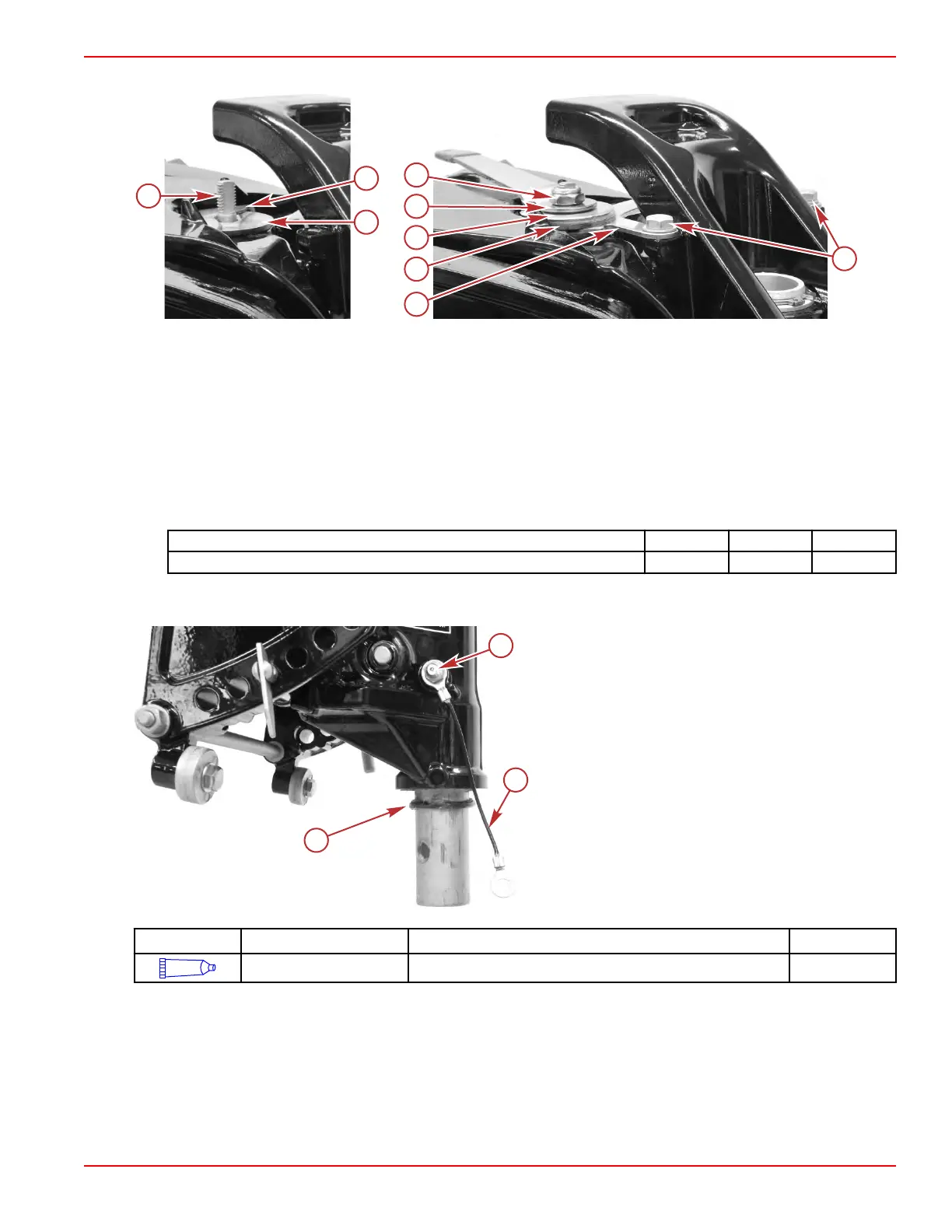
d. Install a disc, handle, washer, and locknut onto the threaded rod. Tighten the locknut to the specified torque.
a - Threaded rod
b - Disc
c - Washer
d - Plate
e - Screws and washers
f - Disc
g - Copilot handle
h - Washer
i - Locknut
Description Nm lb‑in. lb‑ft
Copilot locknut 11.0 97.3 –
4. Lubricate the steering arm O‑ring with 2‑4‑C with PTFE.
5.
Install the O‑ring onto the steering arm shaft.
a - O‑ring
b - Grease fitting
c - Ground continuity wire
Tube Ref No. Description Where Used Part No.
95
2-4-C with PTFE Steering arm O-ring 92-802859A 1
6.
Attach the outboard to the swivel bracket. Refer to Powerhead/Midsection Assembly Separation.
IMPORTANT:
Ensure that the upper mount locknuts are tightened to the specified torque.
Be certain to coat the threads of the tiller handle screws with Loctite® 271 Threadlocker, and ensure that the tiller handle
screws are tightened to the specified torque.
Clamp/Swivel Bracket and Driveshaft Housing
90-8M0125265 eng NOVEMBER 2017 © 2018 Mercury Marine Page 5A-45
 Loading...


