LEFT HAND NON-RATCHETING
Page 6B-56 90-883728 JULY 2001
7. Position gear housing so that the driveshaft is protruding into driveshaft housing.
NOTE: If, while performing Step 8, the driveshaft splines will not align with crankshaft
splines, place a propeller onto propeller shaft and turn it counterclockwise as the gear
housing is being pushed toward driveshaft housing.
8. Move gear housing up toward driveshaft housing while aligning shift shaft splines and
water tube with water tube guide (in water pump cover).
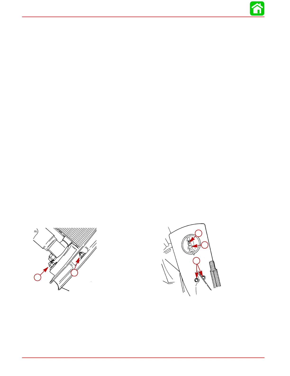
9. Place flat washers onto studs (located on either side of driveshaft housing). Start a
nut (a) on these studs and tighten finger-tight.
10. Start bolt (b) at rear of gear housing inside trim tab recess. DO NOT tighten bolt at this
time.
11. Recheck shift shaft spline engagement and correct if necessary.
IMPORTANT: Do not force gear case up into place with attaching nuts.
12. Evenly tighten 2 nuts (a) which were started in Step 9. Torque to listing in “Torque
Specifications,” preceding.
13. After 2 nuts (located on either side of driveshaft housing) are tightened, check shift
operation as follows:
a. Place guide block anchor pin into forward gear position while turning prop shaft.
Rotate flywheel clockwise (viewed from top); propeller shaft should rotate clock-
wise.
b. Place guide block anchor pin into NEUTRAL position. Propeller shaft should ro-
tate freely clockwise/counterclockwise.
c. Place guide block anchor pin into REVERSE gear position. Rotate flywheel clock-
wise (viewed from top); propeller shaft should rotate counterclockwise.
IMPORTANT: If shifting operation is not as described, preceding, the gear housing
must be removed and the cause corrected.
14. Install washers and nuts (c) onto studs (located on bottom center of anti-cavitation
plate). Torque to listing in “Torque Specifications,” preceding.
51866
c
51873
a
b
d
e
15. Install special flat washer and nut (d) on stud at leading edge of driveshaft housing.
Torque to listing in “Torque Specifications,” preceding.
16. Torque bolt (started in Step 10) to listing in “Torque Specifications,” preceding.
17. Install trim tab, adjust to position in which it had previously been installed, and tighten
bolt (e) securely.
18. Install plastic cap into trim tab bolt opening at rear edge of driveshaft housing.

 Loading...


