ATTACHMENTS / CONTROL LINKAGE
Page 7-28 90-883728 JULY 2001
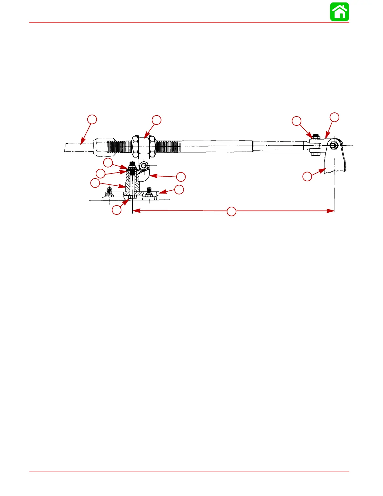
Transom Mounted Ride Guide Attaching Kit Installation
(73770A1)
Attaching Kit Installation
1. Lubricate both holes in pivot block (Figure 1) with Quicksilver 2-4-C with Teflon.
2. Place pivot block on pivot spacer and secure to transom bracket with 3/8 in. x 2-1/2
in. (9.5 mm x 63.5 mm) bolt, flat washer and locknut, as shown in Figure 1. Torque
locknut to 20 Ib. ft. (27 Nm).
a
b
c
d
e
f
g
h
i
j
k
l
Figure 1
a-Ride-Guide Cable
b-Ride-Guide Yoke
c-Pivot Block
d-Pivot Spacer
e-15 in. (381 mm) (Centerline of Attaching Kit Pivot to Centerline of Outboard)
f-Pivot Attaching Locknut [Torque to 20 lb. ft. (27 Nm)]
g-Outboard Steering Arm
h-“Clevis Kit”
i-Ride-Guide Cable Attaching Locknut [Torque to 10 lb. ft. (13.5 Nm)]
j-Bolt [3/8 in. x 2-1/2 in. (9.5 mm x 63.5 mm)]
k-Flat Washer
l-Transom Bracket
 Loading...


