IGNITION SYSTEM
Page 2A-6 90-857138R1 MAY 2000
Description
A single cylinder capacitor discharge ignition (CDI) system is utilized on this model. Major
components of this system are the flywheel/magneto, capacitor charging coil, CDI unit, igni-
tion coil and a spark plug. A stop switch is provided which shorts the trigger coil to ground
preventing ignition from taking place.
Test Procedures
IMPORTANT: When using an ohmmeter for any resistance test, always zero meter
movement whenever scales are changed.
IMPORTANT: If engine misfires, runs rough or does not start, the ignition system
should be checked with a volt meter capable of measuring 400 VDC or higher and di-
rect voltage adaptor (91-89045) or multi-meter/DVA tester (91-99750). Follow instruc-
tions in test manual included with DVA or multi-meter DVA tester.
Direct Voltage Adaptor Specifications
Selector Switch
DVA Leads
1
es
Position
Red Black
o
s
-
Ignition Coil PRI 400 VDC Ground
Black/Yellow
Lead
120-300
Charge Coil 400 VDC
Black/Red
Lead
Ground 150-325
Stop Circuit 400 VDC Brown Lead Ground 175-300
(1)
Reading at cranking and/or idle speed.
IMPORTANT: If DVA or Multi-Meter/DVA Tester is not available, alternate tests can be
performed using an ohmmeter and a Models 9800 Merc-o-tronic Magneto Analyzer
(91-76032), as follows.
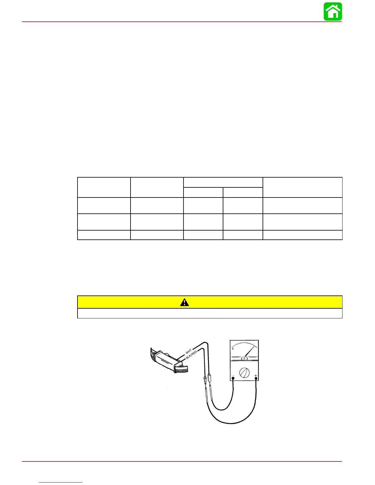
Capacitor Charging Coil
CAUTION
DO NOT rotate flywheel during test or damage to meter may result.
1. Use an ohmmeter to perform the following test.
95-143Ω
2. If meter readings are other than specified, replace capacitor charging coil. Refer to “Igni-
tion Components Removal and Installation,” following.
 Loading...