OIL INJECTION
Page 3C-6 90-855347R1 JANUARY 1999
NOTE: All check valve/hose assemblies for cylinders 2, 4, 6 are brass colored and have
1.250 (31.75 mm) long hoses attached to check valve.
IMPORTANT: Due to the close proximity of the #2 cylinder oil hose to the flywheel,
it will be necessary to trim the length of the #2 oil hose to provide adequate clear-
ance between the oil hose and the flywheel when the check valve assembly is
installed.
9. Trim off #2 cylinder oil hose to an appropriate length (to provide clearance between
hose and flywheel) and install new check valve/hose assembly. Secure hose connec-
tions with sta-straps.
10. Install new check valve/hose assemblies on cylinders #4 and #6. Secure all hose con-
nections with sta-straps.
57410
d
d
d
c
b
a
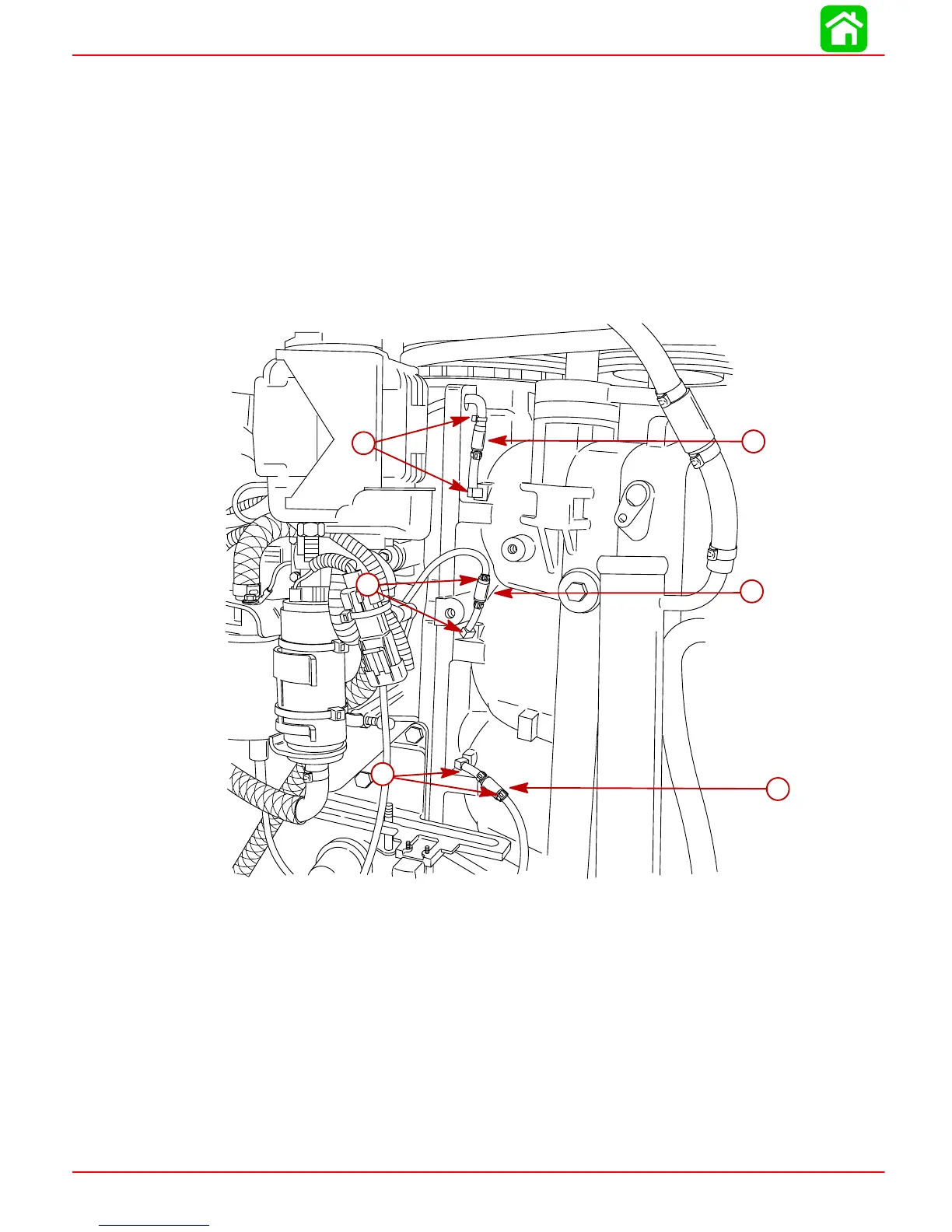
a-#2 Cylinder Oil Hose [Trim hose length as required]
b-#4 Check Valve/Hose Assembly
c-#6 Check Valve/Hose Assembly
d-Sta-straps
 Loading...


