OIL INJECTION
90-855347R1 JANUARY 1999 Page 3C-7
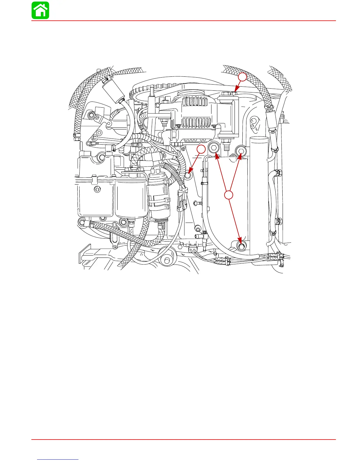
11. Reinstall throttle control arm. Connect throttle link to throttle cam. Torque bolt to 20
lb. ft. (27 Nm).
12. Reinstall oil reservoir. Torque bolts to 170 lb. in. (19 Nm).
13. Reinstall alternator. Torque bolt to 40 lb. ft. (54 Nm).
57409
b
a
c
a-Torque Bolt to 20 lb. ft. (27 Nm)
b-Torque Bolts to 170 lb. in. (19 Nm)
c-Torque bolt to 40 lb. ft. (54 Nm)
14. Reinstall alternator/air compressor belt.
15. Remove Electronic Control Module (ECM) (lay off to one side).
16. Remove solenoid/trim relay plate (lay off to one side).
17. Remove starter motor (lay off to one side).
NOTE: All check valve/hose assemblies for cylinders 1, 3, 5 have a BLUE stripe/band and
a 3.125 in. (79.37 mm) long hose attached to the check valve.
 Loading...


