EasyManuals Logo

Mercury Optimax 150 User Manual

Mercury Optimax 150
522 pages
To Next Page IconTo Next Page
To Previous Page IconTo Previous Page
Page #208 background imageLoading...
Page #208 background image
OIL INJECTION
Page 3C-8 90-855347R1 JANUARY 1999
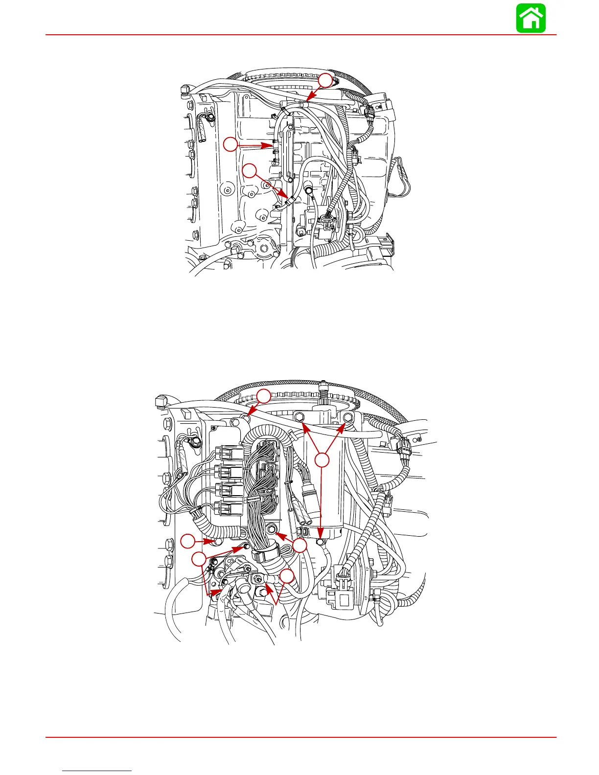
18. Install new check valve/hose assemblies on cylinders #1, #3 and #5. Secure all hose
connections with sta-straps.
57411
a
b
c
a-#1 Cylinder Check Valve/Hose Assembly
b-#3 Cylinder Check Valve/Hose Assembly
c-#5 Cylinder Check Valve/Hose Assembly
19. Reinstall starter motor. Torque bolts to 17.5 lb ft. (23.5 Nm).
20. Reinstall starter solenoid/trim relay plate. Torque bolts to 150 lb. in. (17 Nm).
21. Reinstall ECM. Torque bolts to 70 lb. in. (8 Nm).
57412
a
b
b
c
c
c
a-Torque bolts to 17.5 lb ft. (23.5 Nm)
b-Torque bolts to 150 lb. in. (17 Nm)
c-Torque bolts to 70 lb. in. (8 Nm)
22. Reinstall bottom cowling.
23. Reinstall flywheel cover.

Table of Contents

Questions and Answers:

Question and Answer IconNeed help?

Do you have a question about the Mercury Optimax 150 and is the answer not in the manual?

Mercury Optimax 150 Specifications

General IconGeneral
Horsepower150 HP
Engine TypeV6
Alternator Output60 amp / 756 watt
StartingElectric
SteeringRemote
Displacement2.5 L
Fuel Induction System2-Stage Direct Fuel Injection (DFI)
Shaft Length20", 25"
Dry Weight431 lbs (20 in), 439 lbs (25 in)

Related product manuals