Page 13 of 47
3.2 Gas Ports
On the bottom of the FTC320 housing two tubes with 6mm outer diameter for gas connection are lo-
cated. They are labeled with “GAS IN “ and “GAS OUT“.
For low requirements regarding gas tightness and resistance to pressure, the tubes can be used as
hose connectors. For permanent gas and pressure tightness compression fittings are recommended
(e.g. by “Swagelok“©).
After connecting the device, a leakage test should be performed (especially when working with flammable
and/or toxic gases).
3.3 Electrical Connectors and Ground
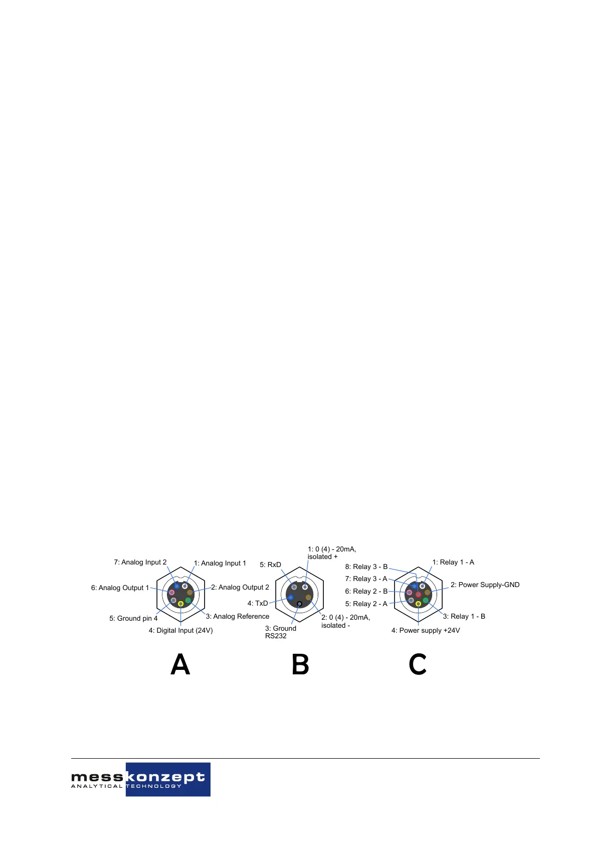
1: Analog Input 1
2: Analog Output 2
3: Analog Reference
4: Digital Input (24V)
5: Ground pin 4
6: Analog Output 1
7: Analog Input 2
1: 0 (4) - 20mA,
isolated +
2: 0 (4) - 20mA,
isolated -
3: Ground
RS232
4: TxD
5: RxD
1: Relay 1 - A
2: Power Supply-GND
4: Power supply +24V
3: Relay 1 - B
7: Relay 3 - A
6: Relay 2 - B
5: Relay 2 - A
8: Relay 3 - B
A
B C
Figure 3.2: Electrical connector pin assignments of the three connectors on the FTC320
The FTC320 has three plug connectors as shown in Figure 3.2. The cables (712, IP67) with molded
connector plug and a length of two meters (five meters available on request) are part of the purchased
parts package. The cables have open ends. The cross-section of the conductors in cable A and C is
0,14mm
2
, for cable B 0,25mm
2
. Cable A is shipped with devices set up for analog output.
The protection class of the device is only effective with all cables attached. In case cable
A is not used, connector plug A must closed with an end fitting.
3.3.1 Requirements for Electrical Connectors
Before using the device make sure that the power supply is in accordance with the
specifications of the device and that all electric connections correspond to the information
given in this manual.
The FTC320 is a device of protection class III. For power supply a source with PELV specification (Pro-
tective Extra Low Voltage) according to EN 60204-1 must be used. See also Section 3.3.2 "Ground".
The potential-free relay contacts must also be monitored with a power supply unit with PELV specifica-
tion.
File name:
FTC320 Operating Manual_1.09KD201009MPO5V04.pdf