Page 14 of 47
3.3.2 Ground
ERROR
MAINT REQ
POWER
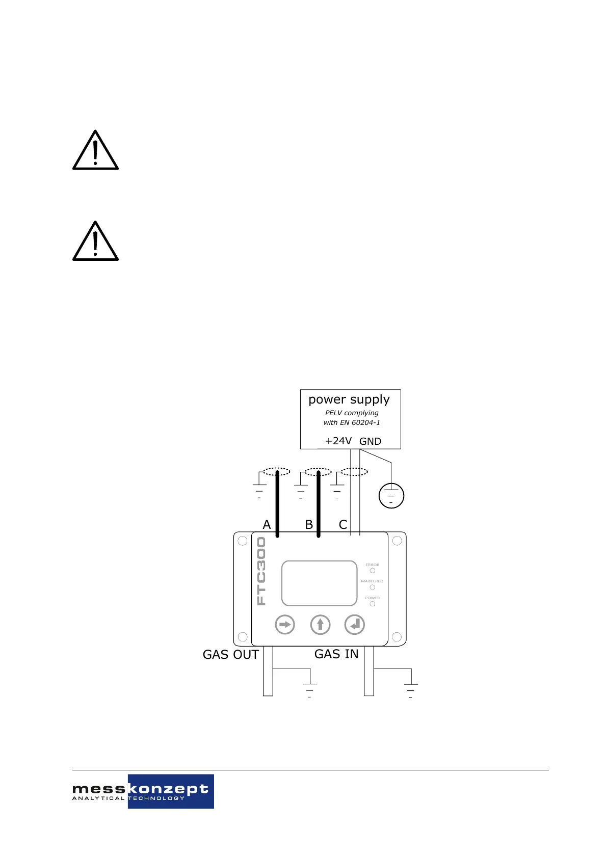
power supply
PELV complying
with EN 60204-1
+24V
GND
A
B C
GAS OUT
GAS IN
Figure 3.3: Grounding the FTC320
To comply with EN 60204-1 and to ensure your device’s function, the device has to be installed such
that the power supply (PELV) is connected to protective earth (PE) with its ground conductor, see
Figure 3.3. The shielding of cables A, B and C should be connected to functional ground. Dependent
on the circumstances, gas inlet and gas outlet can be grounded in addition. Connections to the ground
should be made with short low-resistant cables of large diameter.
3.3.3 Data exchange via serial interface (RS-232)
The serial interface, often called UART (Universal Asynchronous Receiver Transmitter), is based on the
RS-232 standard. The point-to-point data transmission is carried out via the two TxD (Transmit Data)
and RxD (Receive Data) wires to be crossed with a common ground line (GND) for both devices. This
creates a bidirectional bus that allows full-duplex communication. The communication partners can
therefore send and receive data simultaneously.
Data transmission via UART is performed with a fixed data frame (UART frame). This frame must be
known to both communication partners. It consists of: A start bit, 5-9 data bits, an optional parity bit and
one or two stop bits. If a PC is connected to the analyzer, the necessary settings are typically identified
automatically. If this is not the case, the parameters can be set manually according to Table 9.2. (see
Section 9.1).
Only a few PCs are still delivered with a so-called COM port (serial RS-232 interface). To be able to
operate and program devices that have an RS-232 interface with computers without this, use of con-
File name:
FTC320 Operating Manual_1.09KD201009MPO5V04.pdf