42
2.5.3.1 Start-up parameters – Params 12 System Start
• External/default parameters: during each start-up phase the system must be initialised by the master, which sends all configuration parameters
such as input/output type, etc.
• Saved parameters: at he parameters sent by the master are permanently saved in the device and used for subsequent startup phases.
2.5.3.2 Analogue output display – Params 13 Endianess
Makes it possible to choose between two display modes for the two bytes containing the analogue value.
• Motorola or big-endian logic: storage that starts from the most significant byte and finishes with the least significant byte (default).
• INTEL or little-endian logic: storage that starts from the least significant byte and finishes with the most significant byte.
2.5.3.3 Analogue input data format - Params Analog Input Format
Enables the analogue input data format to be set in two modes:
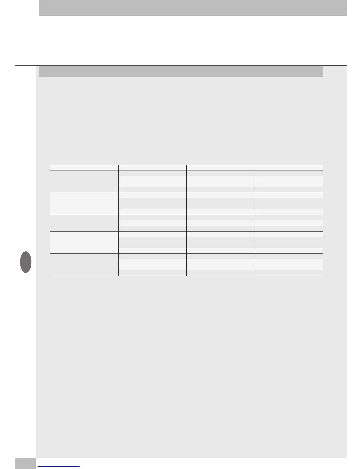
• 16 bit (Sign + 15 bit) - the analogue value is between +32767 and -32768 which is obtained with the maximum analogue value permitted by the
type of input.
The values are outlined in the table.
Analogue value Digital value Signal
Input type -10… + 10 V
+11.7 V 32767 Overflow
+ 10 V
-10 V
28095
- 28095
Nominale range
-11.7 -32768 Underflow
Input type -5… + 5 V
+5.8 32767 Overflow
+ 5 V
- 5 V
28095
- 28095
Nominale range
-5.8 -32768 Underflow
Input type 1… + 5 V
+5.8 32767 Overflow
+ 5 V 28095 Nominale range
0 V 0 Underflow
Input type -20 mA … + 20 mA
+23 mA 32767 Overflow
+20mA
- 20mA
28095
- 28095
Nominale range
-23 mA -32768 Underflow
Input type 4 mA … + 20 mA
+23 mA 32767 Overflow
20mA
4 mA
27307
5513
Nominale range
0 mA 0 Underflow
• Linear scaled – the analogue value measured refers to the value set in the user full scale range.
Can be set individually for each analogue channel. (See 3.3.4.4 User full scale).
2.5.3.4 Enable of I4.0 diagnostic - Param 15 I4.0 enable
It allows to enabled the I4.0 diagnostic functions.
For a complete description of the functions, see the "EB 80 USER MANUAL of Industry 4.0 EtherNet/IP functions".
2.5.3.5 Valves data refresh time - Param 16 valves data refresh time (ms)
2.5.3.6 Actuators data refresh time - Param 17 Actuators data refresh time (ms)
2.5.3.7 Setting specific parameters of the modules – Parameters object type
20 objects are available for module parameters – Object 1-20
The module to be configured must be selected from those available in the list Object type.
To use the specific parameters, each object must be enabled by selecting "user values" in the Parameter Type.
• Each object can contain the parameters of the following modules:
• from 8 to 128 coils – 008 to 128 coils;
• from 1 to 6 of 8 Digital Inputs modules – No.1 to No.6 08 Digital Inputs 02282S01;
• from 1 to 3 of 16 Digital Inputs modules – No.1 to No.3 16 Digital Inputs 02282S06;
• from 1 or 2 of 4 Analogue Inputs modules - No.1 to No.2 04 Analog Inputs 02282S04;
• 1 of 4 Analogue Inputs module for temperature measurement - No.1 04 Temperature Inputs 02282S08;
• from 1 to 9 of 8 Digital Outputs modules – No.1 to No.9 08 Digital Outputs 02282S02;
• from 1 to 9 of 6 Digital Outputs modules – No.1 to No.06 Digital Outputs 02282S03;
• from 1 to 4 of 16 Digital Outputs modules – No.1 to No.4 16 Digital Outputs 02282S07;
• 1 of 4 Analogue Outputs module - No.1 04 Analog Outputs 02282S05;
• 1 of Actuator module for I 4.0 diagnostic – No.1 Actuator.
3 objects contain up to 16 parameters, the other 17 contain up to 36 parameters.
Parameters can be configured by setting the number of the object corresponding to the module in the Object ID.
GB