45
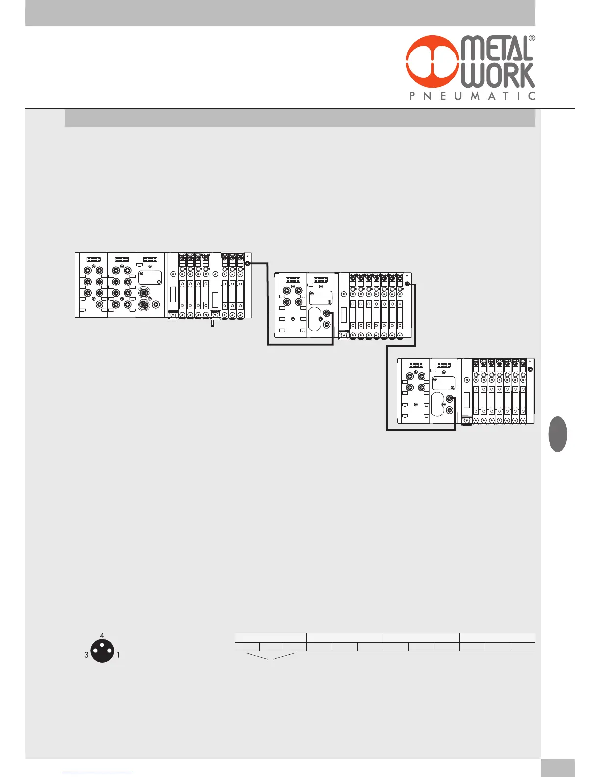
3.2.2 Addressing the Additional Electrical Connection - E0AD
All the modules are addressed in sequence.
• Addressing valve solenoid pilots - from the first solenoid pilot of the EtherNet/IP node to the last solenoid pilot of the last-in-line additional island.
• Addressing digital input S modules - from the first module connected to the EtherNet/IP node to the last digital input S module of the last-in-line
additional island.
• Addressing digital output S modules - from the first module linked to the EtherNet/IP node to the last digital output S module of the last-in-line
additional island.
• Addressing analogue input S modules - from the first module linked to the EtherNet/IP node to the last analogue input S module of the last linked
additional island.
• Addressing analogue output S-modules - from the first module linked to the EtherNet/IP node to the last analogue output S module of the
last-in-line additional island.
DO 1-6 DI 1-8 E1 E7
AI 1-4 E8 E15
AI 5-8 E16 E23
3.3 SIGNAL MODULES - S
EB 80 systems are supplied with numerous modules for controlling input or output signals.
These modules can be added to systems with either a EtherNet/IP electrical connection or ones with Additional Electrical Connection.
Modules with both digital and analogue inputs and outputs are available.
3.3.1 Digital Input modul
Digital 8-Input M8 module: each module can handle up to 8 digital inputs. It is defined with 1 byte, starting from byte In 1.
16 digital input terminal board module: each module can handle up to 16 digital inputs. It is defined with 2 byte, starting from byte In 97.
Each input has a certain number of parameters that can be configured individually .
The digital input module makes it possible to read digital inputs with a maximum signal exchange frequency of 1kHz.
High-frequency reading is possible for all inputs, with up to a maximum of 2 modules connected to the EB 80 network.
3.3.1.1 Type of inputs and power supply
Two- or three-wire digital PNP or NPN sensors can be connected. The sensors can be supplied by either a EtherNet/IP node or Additional
Electrical Connection power supply. In this way the sensors remain active even when the valve auxiliary power supply is switched off.
3.3.1.2 Electrical connections
Pin assignment of M8 connector Pin assignment of terminal board connectors
3.3.1.3 Polarity
The polarity of each input can be selected as follows:
• Value
= 0 PNP, the signal is active when the signal pin is connected to +VDC.
• Value
= 1 NPN, the signal is active when the signal pin is connected to 0VDC.
The signal LED light is ON when the input is active.
Example of configuration of the first connected S module, with 8 PNP inputs: Polarity Module 1 = 0
Example of configuration of the first connected S module, with 4 inputs: X1...X4 PNP e 4 ingressi X5...X8 NPN: Polarity Module 1 = 240
1 = +VDC (Sensor power supply)
3 = GND (Sensor power supply)
4 = Input
Input X1 - X5 - X9 - X13 Input X2 - X6 - X10 - X14 Input X3 - X7 - X11 - X15 Input X4 - X8 - X12 - X16
+ Input 0 + Input 0 + Input 0 + Input 0
Sensor power supply
GB