47
Example of configuration
:
Operating state
Bit 7 Bit 6 Bit 5 Bit 4 Bit 3 Bit 2 Bit 1 Bit 0
IN 8 IN 7 IN 6 IN 5 IN 4 IN 3 IN 2 IN 1
NO NO NC NO NC NC NC
0 0 1 0 0 1 1 1
bin 00100111 = 39 dec
Input filter
Bit 7 Bit 6 Bit 5 Bit 4 Bit 3 Bit 2 Bit 1 Bit 0
IN 4 IN 3 IN 2 IN 1
2 = 10 ms 2 = 10 ms 3 = 20 ms 3 = 20 ms
1 0 1 0 1 1 1 1
bin 10101111 = 175 dec
3.3.2.1 Type of output and power supply
Can be used to control different digital devices. The following devices are compatible:
• Solenoids
• Contactors
• Indicators
The outputs are powered by the EtherNet/IP node power supply, if any, the digital 6-ouput M8 Module and the previous power supply
(see 3.3.3).
Check that the inrush current and continuous currents of the connected devices do not exceed the currents supplied to each connector and the
maximum current of the module.
If the module is connected directly to the electrical EtherNet/IP connection, the power supply is the same as that of the EtherNet/IP node.
Use suitable external protection to avoid permanently damaging the device.
3.3.2.2 Electrical connections
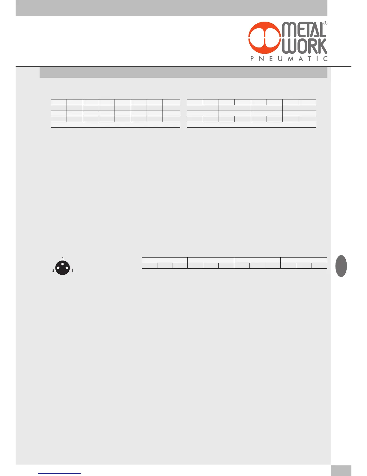
Pin assignment of M8 connector Pin assignment of terminal board connectors
3.3.2 Digital Output module
Digital 8-Output M8 module: each module can handle up to 8 digital outputs. It is defined with 1 byte, starting from byte Out 16.
16 digital Output terminal board module: each module can handle up to 16 digital outputs. It is defined with 2 byte, starting from byte Out 86.
Each output has some parameters that can be configured individually, by selecting the module in the page entitled "Overview of Devices →
Properties → Parameters of the Unit".
3.3.2.3 Polarity
The polarity of each output can be selected as follows.
• Value
= 0 - PNP, when the output is active the signal pin shows +VDC. To power a load it is necessary to connect the other end to 0VDC.
• Value
= 1 - NPN, when the output is active the signal pin shows +0VDC. To power a load it is necessary to connect the other end to +VDC.
3.3.2.4 Operating state
The operating state of each output can be selected as follows:
• Value
= 0 - Normally Open, the output is active when it is controlled by the control system. The Led light is on when the output is controlled.
• Value
= 1 - Normally Closed, the output is active when it is NOT controlled by the control system. The Led light is active then the output is
NOT controlled.
Example of configuration of the first connected S module, with 8 NC outputs: Operating state = 255
Output X1 - X5 - X9 - X13 Output X2 - X6 - X10 - X14 Output X3 - X7 - X11 - X15 Output X4 - X8 - X12 - X16
+ Output 0 + Output 0 + Output 0 + Output 0
1 = +VDC (COM for OUT NPN)
3 = GND (COM for OUT PNP)
4 = Output
GB