58
4. DIAGNOSTICS
The diagnosis of the EB 80 EtherNet/IP system is defined by the state of the interface LED lights. Each component in the system relays its state, locally
by LED lights, and to the EtherNet/IP node by software messages.
4.1 EtherNet/IP NODE DIAGNOSTIC MODE
The diagnosis of the EB 80 EtherNet/IP system is defined by the state of the interface Led MS, NS e IN/OUT.
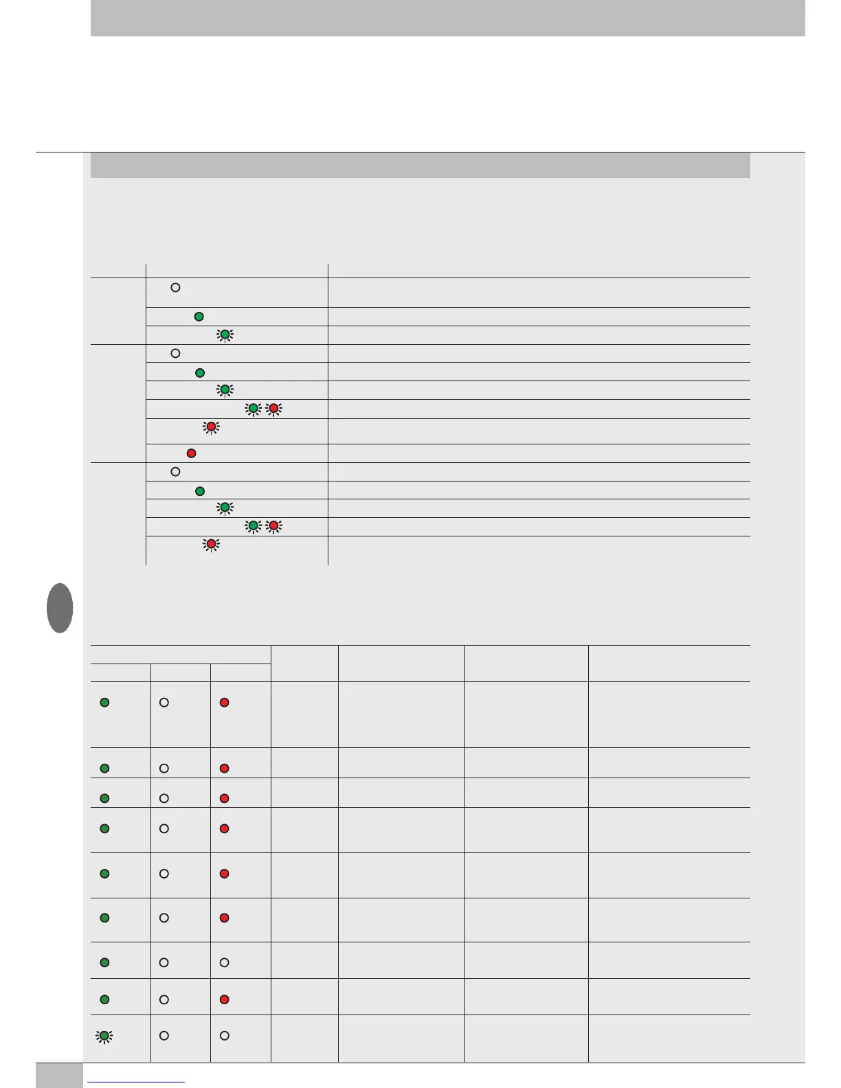
Led STATUS Meaning
IN / OUT
link/act
OFF
No connection to the EtherNet/IP.
With power ON, the MS light flashes red and the NS light stays steady red.
ON (
green)
The module is connected to the network but there is no data exchange
GREEN (
flashing)
The module is communicating correctly with the network
MS
OFF
No power or communication initialization
ON (
green)
The module is operating correctly
GREEN (
flashing)
The module is connected but not configured correctly on the network
GREEN / RED (
flashing)
On switching on the module performs an auto-test.
RED (
flashing)
Configuration error, e.g. an IP address assignment error has been detected.
Another user uses the same IP address in the network.
ON (
red)
Module operating fault
NS
OFF
Incorrect communication initialisation or module configuration in the network
ON (
green)
Correct EtherNet/IP connection
GREEN (
flashing)
Communication with the master network is down
GREEN / RED (
flashing)
On switching on the module performs an auto-test.
RED (
flashing)
The connection previously established with the network
Master is timed out or discontinued. Connection can be resumed by restarting communication.
4.2 EB 80 SYSTEM DIAGNOSTIC MODE – ELECTRICAL CONNECTION
Diagnosis of the EB 80 system - Electrical Connection - is defined by the state of Power, Bus Error and Local Error LED lights.
Diagnostic functions of the EB 80 system relay the state of the system via error codes in hexadecimal or binary format to the controller, in order of
priority. The state byte is interpreted by the controller as an input byte.
The table below shows the correct interpretation of the codes.
LED light state Hex code Meaning Notes Solution
Power Bus Error Local Error
ON (green) OFF ON (red)
0xFF
System limits exceeded,
comunication line data
overflow
Number of I/Os to be checked
simultaneously is too high or
the control frequency is too
high.
Modify the system by reducing the
number of I/Os to be checked
simultaneously.
Contact technical support
ON (green) OFF ON (red)
0xD4 ÷ 0xD7
fault with a temperature
analogue input module
• Sensor not connected
• Wrong parameters
Check the connection and the
parameters set
ON (green) OFF ON (red)
0xD0 ÷ 0xD3
Analogue input module not
calibrated
- Contact technical support
ON (green) OFF ON (red)
0xCC ÷ 0xCF
Fault with analogue output
or total module current
too high
Individual output fault/
module over-demand/
DAC errors
Turn off power supply and remove the
cause of failure
ON (green) OFF ON (red)
0xC8 ÷ 0xCB
Fault with analogue input
or total module current
too high
Under-overflow out of range
single input / over-absorption
of the module
Turn off power supply and remove the
cause of failure
ON (green) OFF ON (red)
0xB0 ÷ 0xC5
Digital output failure or total
current of module too high
Short-circuit of an individual
output / module overcurrent
Turn off power supply and remove the
cause of failure
ON (green) OFF OFF
0xA0 ÷ 0xAF
Overcurrent of a digital input Signalled by one input Turn off power supply and remove the
cause of failure
ON (green) OFF ON (red)
0x20 ÷ 0x9F
Valve 1 / 128 faulty
**
Solenoid pilot short-circuited,
interrupted or not connected
Turn off power supply and remove the
cause of failure
GREEN
(flashing)
OFF OFF
0x17
No auxiliary power - Insert auxiliary power supply
GB