64
GB
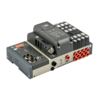
6.4 SIGNAL MODULES - S - DIGITAL OUTPUTS + ELECTRICAL POWER SUPPLY
TECHNICAL DATA 6 M8 Digital Outputs + Electrical power supply
Supply voltage range V 12 -10% 24 +30%
Minimum operating voltage V
10.8
*
Maximum operating voltage V 31.2
Maximum admissible voltage V
32
***
Output voltage Corresponding to power voltage
Current for each connector mA max 1000
Current for each module mA max 4000
Type of output Software-configurable PNP/NPN
Protection Overload and short-circuit protected inputs
Connections 6 M8 3-pole female connectors for Signals
1 M8 4-pole male connector for Supply
Input active signals One LED for each input
* Minimum voltage 10.8V required at solenoid pilots. Check the minimum voltage at the power suply output using the calculations see page 37.
*** IMPORTANT! Voltage greater than 32VDC will damage the system irreparably.
6.5 SIGNAL MODULES - S - ANALOGUE INPUTS
TECHNICAL DATA 4 M8 Analogue Inputs
Sensor supply voltage Corresponding to power voltage
Current for each connector mA max 200
Current for each module mA max 650
Type of input, software configurable 0/10 V; 0/5 V; +/-10 V; +/-5 V; 4/20 mA; 0/20 mA
Protection Overload and short-circuit protected inputs
Connections 4 M8 4-pin female connectors
Local diagnostic signal via LED Overload, short-circuit or type of input
not complying with the configuration
Digital convert resolution 15 bit + prefix
6.6 SIGNAL MODULES - S - ANALOGUE OUTPUTS
TECHNICAL DATA 4 M8 Analogue Output
Supply voltage for devices Corresponding to power voltage
Current for each connector mA max 200
Current for each module mA max 650
Type of output 0/10 V; 0/5 V; +/-10 V; +/-5 V; 4/20 mA; 0/20 mA
Protection Overload and short-circuit protected outputs
Connections 4 M8 4-pole female connectors
Local diagnostic signal via LED Overload, short-circuit or type of connection
not complying with the configuration
Digital convert resolution 15 bit + prefix