12
SYSTEM
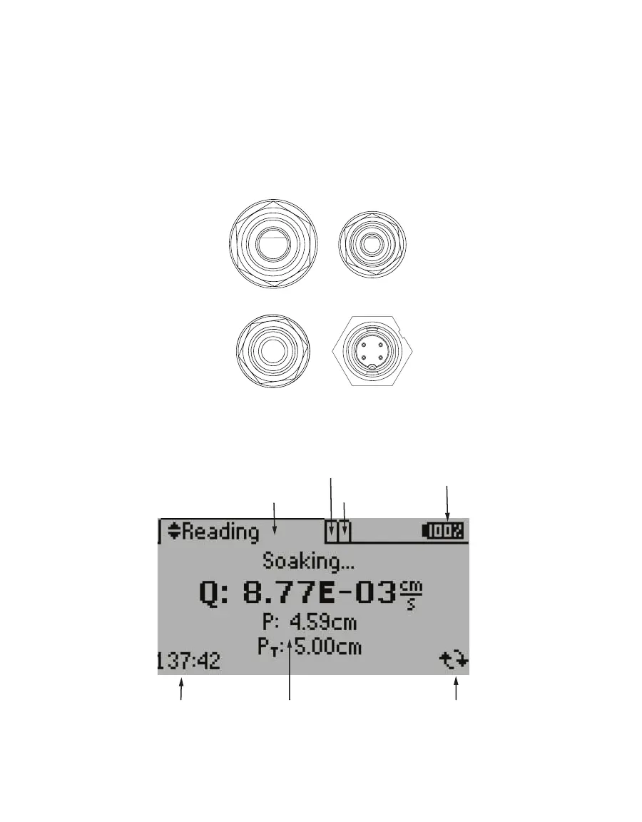
There are four connections on the control unit (Figure12):
• Top left connection is for the 7.9-mm (5/16-in) water input (water tank to control unit).
• Bottom left connection is for the 9.5-mm (3/8-in) water output (control unit to
infiltrometerhead).
• Bottom right connection is for the sensor connection to the infiltrometer head.
• Top right connection is a 6.4-mm (1/4-in) air output (control unit to infiltrometer head).
Water input
Water output
Air input
Sensor
connection
Figure12 Control unit connections
The SATURO display (Figure13) features three main tabs designed for ease of use: Reading,
Configuration, and Data.
Time remaining Test status
Active tab
Battery level
Live updating
Data tab
Figure13 SATURO display elements