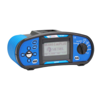
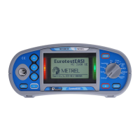
MI 2087 AL2 EasiTEST Introduction
5
1.3 List of parameters measurable by the EasiTest
Parameter Switch
position
Description
Insulation resistance
INSULATION Test voltage: 250 V, 500 V, 1000 V
Continuity resistance of
protective conductors
CONTINUITY
- Test current: > 200mADC
- Single measurement
- Auto polarity reverse
Fault loop resistance RL-PE
LOOP L-E,
PSC
- Max. test current 2,5 A
Fault loop prospective
short-circuit current Ipsc
LOOP L-E,
PSC
- Calculation:
Ipsc = UN⋅1,06/RL-
Voltage UL-PE
LOOP L-E,
PSC
- 0 ÷ 264 V
Line resistance RL-N
LOOP L-N,
PSC
- Max. test current 2,5 A
Line prospective
short-circuit current Ipsc
LOOP L-N,
PSC
- Calculation:
Ipsc = UN⋅1,06/RL-
Voltage UL-N
LOOP L-N,
PSC
- 0 ÷ 264 V
RCD - Contact voltage Uc
TRIP-LOCK - Without test rod
- No trip-out RCD
RCD -
RL (external source)
TRIP-LOCK - Without test rod
- No trip-out RCD
RCD - Trip-out time t∆N
RCD
MANUAL
- At 0,5I∆N, I∆N, 2I∆N
(multiplier 5 is not available, if
I∆N = 1000 mA)
RCD – Trip-out current I∆
RCD
RAMPTEST
- Rising current
(0,2 ÷ 1,1)I∆N
RCD - Trip-out time t∆ at
trip-out Current I∆
RCD
RAMPTEST
RCD - Automatic test
RCD AUTO
- Contact voltage
measurement
- Trip-out time measurement
at 0,5I∆N, I∆N and 5I∆
(both test curr. start phases)
 Loading...