MI 2087 AL2 EasiTEST Measurement instructions
15
Notes:
q In case that present external voltage higher than 29V (AC or DC) ia present
between test terminals the insulation resistance measurement will not be
carried out after pressing START key, but the voltage will be displayed,
equipped with “!” mark! Warning sound is also emitted.
q Tested object is discharged automatically after finishing the measurement,
actual voltage is displayed during discharging until the voltage drops below
30V!
q If test result is out of measurement range (open test leads or good isolation)
“>1000 MΩ” message will be displayed!
q Positive pole of test voltage is attached to blue test lead (Universal test cable)
or to commander test tip (Tip Commander)!
q “bat” message displayed during or after finishing the measurement means
batteries are too weak to guarantee correct result. Replace the batteries.
3.2 Continuity of protective conductors
Continuity of protective conductors has to be measured before mains voltage is
connected to tested installation (new or adapted installations). Max. allowed
resistance value depends on power of connected loads, used installation system (TN,
TT) etc.
For additional general information concerning Continuity measurement, refer to
enclosed handbook Measurements on electric installations in theory practice.
Warning:
q Make sure that tested object is deenergised (mains voltage disconnected)
before starting the measurement!
How to carry out the measurement
Step 1
q Connect test cable (Universal test cable or Tip Commander) to EasiTest.
q Set function switch to CONTINUITY position, the following menu will be
displayed:
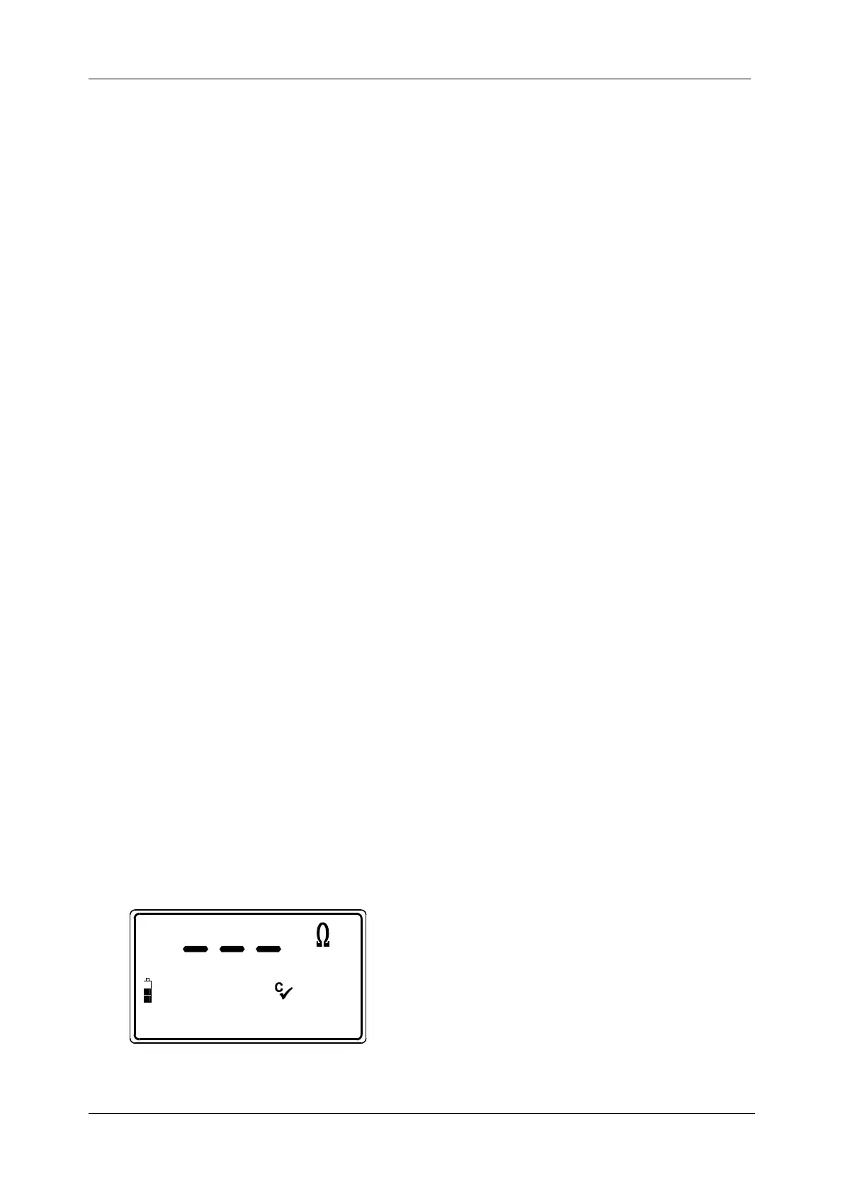
Fig. 7: Continuity of protective conductors initial menu
Cü........Resistance of test leads has
been compensated.
 Loading...