MG-MINA/LINA/750-LFC GRID ASSEMBLY GUIDE
65
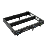
MUB-MINA/LINA FLOWN CONFIGURATIONS
The MUB-MINA/LINA U-bracket with up to two LINA can be flown from a truss with two C-clamps attached to the bracket’s
two 1/2-inch center holes (see Table 11). Make sure to use rigging hardware rated to meet or exceed the weight of the U-
bracket and suspended loudspeakers.
For flown configurations, the MUB-MINA/LINA can be oriented for either maximum downtilt (with the slot near the front of
the loudspeakers) or maximum uptilt (with the slot near the rear of the loudspeakers).
• For a single flown cabinet, the MUB-MINA/LINA supports continuous angles of 0 to –20 degrees in the maximum down-
tilt orientation, and angles of +10 to –10 degrees in the maximum uptilt orientation.
• For two flown cabinets, the MUB-MINA/LINA supports fixed angles of +10, 0, –5, –10, and –20 degrees with either orien-
tation.
CAUTION: Up to two cabinets may be flown using the two center 1/2-inch holes with the load evenly distrib-
uted on the two points. Use MAPP to verify rigging configurations.
NOTE: For two flown cabinets, the MUB-MINA/LINA slot is not recommended for variable adjustments,
because the angle could change over time due to the weight of the cabinets.
NOTE: For illustrations showing which MUB-MINA/LINA mounting holes and slot configurations to use to
achieve specific angles for flown applications, see Table 12 and Table 13 on page 60.
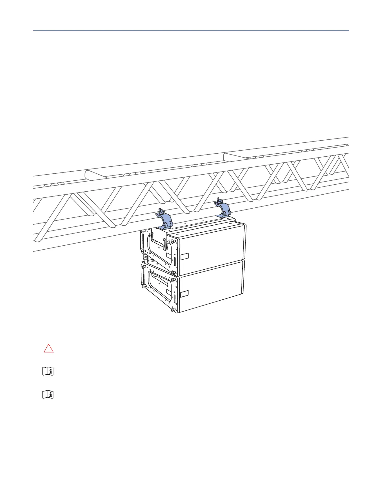
Figure 57: Flown MUB-MINA/LINA with Two LINAs
 Loading...