27
CHAPTER 6: FLYING ARRAYS
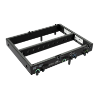
MG-MINA/LINA/750-LFC GRID ORIENTATIONS FOR FLOWN CONFIGURATIONS
The orientation of the MG-MINA/LINA/750-LFC grid allows placement of the array’s center of gravity closer to the front or
rear of the grid, thereby determining the maximum downtilt or uptilt available for the flown array.
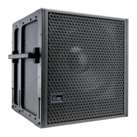
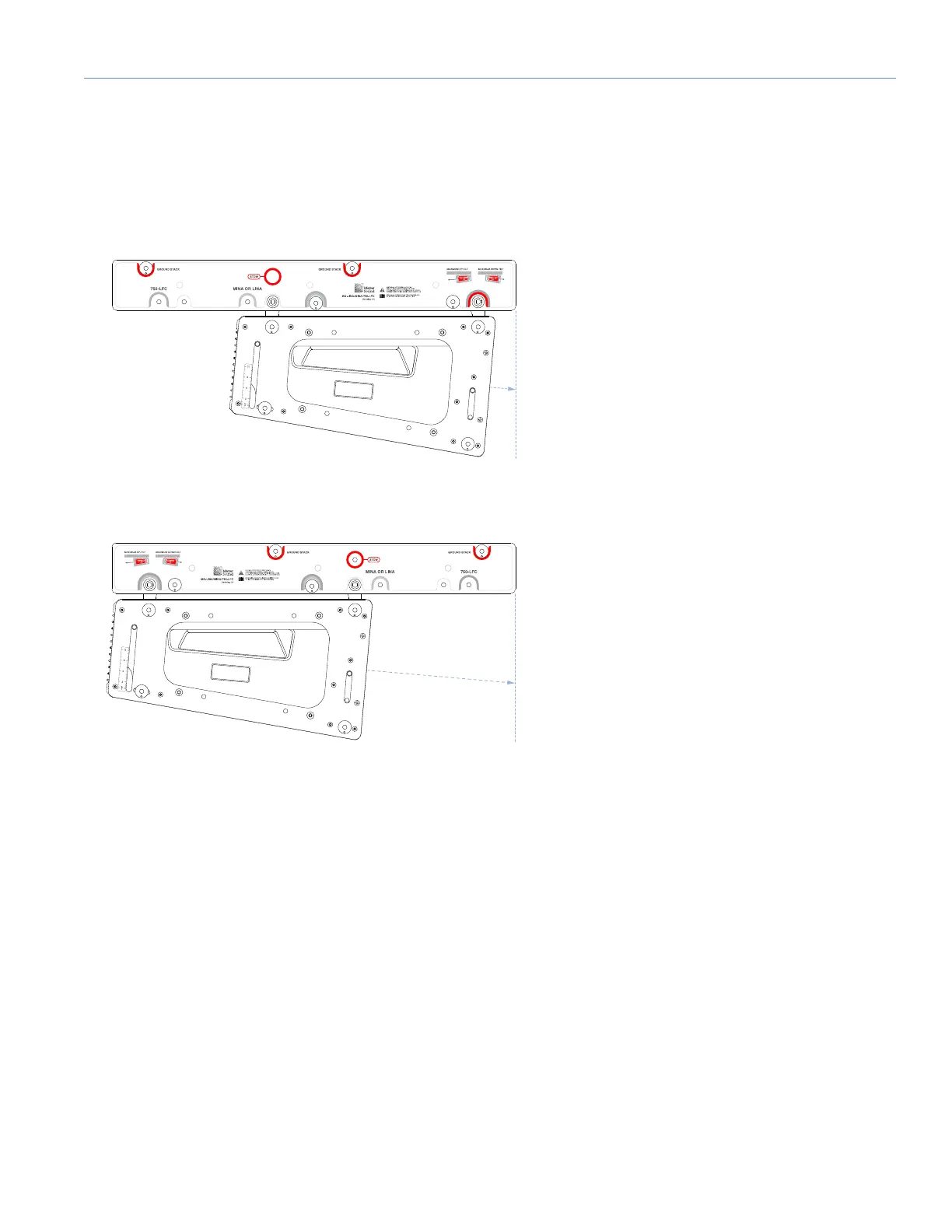
MG-MINA/LINA/750-LFC Oriented for Maximum Array Downtilt
When the MG-MINA/LINA/750-LFC grid is oriented so the loudspeaker mounts closer to the front of the grid, the array’s
center of gravity moves closer to the front of the grid. The grid's rear pickup points can then be used to achieve maximum
array downtilt. The label on the MG-MINA/LINA/750-LFC shows this configuration as “Maximum Downtilt.” Using the maxi-
mum downtilt orientation, the LINA at the top of the array can be attached relative to the grid at 0 and –5 degree (downtilt).
Figure 18: LINA Closer to Front of MG-MINA/LINA/750-LFC for Maximum Array Downtilt
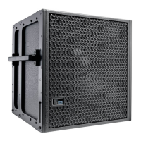
Figure 19: LINA Closer to Rear of MG-MINA/LINA/750-LFC for Maximum Array Uptilt
 Loading...