MFJ-269C Instruction Manual LF/HF/VHF/UHF SWR Analyzer
8
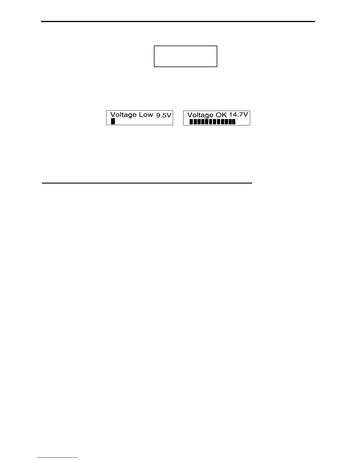
The third message is a voltage check. It displays the operating voltage, indicating battery condition or the
voltage of your external power supply.
The fourth and final screen is the first "working display" (Complex Impedance). The two analog panel
meters also activate when the working display comes up.
3.3 Main Measurement Modes (LF/HF/VHF, 0.53-230 MHz)
Momentarily pressing (or tapping) the Mode button after the first working display appears allows you to
scroll through all five basic measurement modes provided by the MFJ-269C. The opening mode is
Impedance R & X (resistance and reactance). As each new mode comes up, its title screen appears for
about two seconds, and then the companion data screen appears. Each of the five Basic Modes are listed
below:
1. Impedance R&X: This is the analyzer's "default mode", and it is the function most commonly used.
The top line of the data screen displays Frequency in MHz and SWR, while the bottom line shows
complex impedance where Rs equals the load's series resistive component and Xs shows the load's series
reactive component. In this function, the analog SWR and Impedance Meters (Z) are also activeated.
2. Coax Loss: Pressing Mode once brings up the Coax Loss -- followed by the data screen. The top line
shows Frequency in MHz and the bottom line displays Coax Loss in dB.
3. Capacitance in pF: The third mode displays Frequency in MHZ on the top line, followed by Xc
(capacitive reactance) on the bottom line. The analog meter also shows reactance X.
4. Inductance in μH: The fourth mode, Frequency appears on top and X
L (inductive reactance) on the
bottom. Meter shows reactance (X).
5. Freq. Counter: The fifth function turns off the analyzer's internal oscillator and routes the input of the
counter to the BNC connector labeled Frequency Counter Input. In this mode, the top line of the LCD
display shows the measured Frequency in MHz and the counter's Gate Time in seconds.
Important Note: Section-4 of this manual provides detailed instructions for using each of the five basic
operating modes described above. To ensure accurate measurement and avoid the possibility of
inadvertent damage, please read through this section carefully before operating the analyzer!
MFJ Enterprises
(c) 2014