MFJ-269C Instruction Manual LF/HF/VHF/UHF SWR Analyzer
14
2. Connect the capacitor across the Antenna connector with the shortest leads possible, or include the
lead length normally used in the actual circuit to include stray lead inductance in your measurement.
3. Adjust the VFO (Tune) to your frequency of interest. If a range warning comes up, find the closest
frequency where no warning appears. Warnings are C(Z>650), C(X<7), and C(X=0) -- and the C(X=0)
warning indicates the capacitor appears as a near-perfect short.
When measuring a capacitor, it's displayed value in pF will typically change with the test frequency. This
change occurs because stray inductance inside the capacitor and in the wires leading to the analyzer
calibration plane are in series with it. The actual value (in pF) for most capacitors does increase with
frequency and may reach infinity when the capacitive element and its stray inductance become series-
resonant. This frequency is called the device's Series Resonant Frequency (where X=0). Bypass
capacitors are sometimes intentionally operated at or near this frequency, but for most applications, the
frequencies will be far below it. In addition to the display, the analyzer's Impedance meter displays the
reactance (X in ohms) of the capacitor.
4.5 Inductance (Function-4)
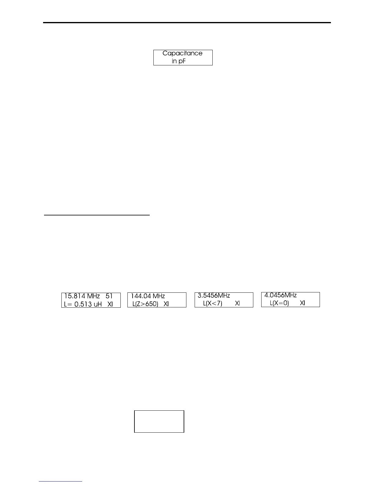
Access the Inductance mode by stepping the Mode switch to the Inductance identification screen. The
top line of the working display shows the Frequency in MHz and the Inductive Reactance (X
L) of the
DUT at that particular frequency. The lower line shows the Inductance in uH. Inductance is calculated
using the measured Reactance (X
L) and the VFO frequency.
Important Note: Measurements become inaccurate below 7 ohms or above 650 ohms. If component
reactance falls into an inaccurate range, the error messages L(X<7), L(X=0) or L(Z>650) will be
displayed.
Reactance Sign: The MFJ-269C measures reactance (X) and mathematically converts it to an inductance
value X
L, but the processor can't actually determine if the reactance it measures is inductive or capacitive.
You can usually confirm the sign by adjusting the VFO. If tuning down in frequency decreases reactance,
the reactance is likely inductive (+jX) because inductors normally exhibit decreased reactance with a
decrease in frequency.
To measure an Inductor:
1. Turn the analyzer on and step the Mode switch three times to bring up the Inductance identification
screen.
Inductance
in uH