MFJ-269C Instruction Manual LF/HF/VHF/UHF SWR Analyzer
9
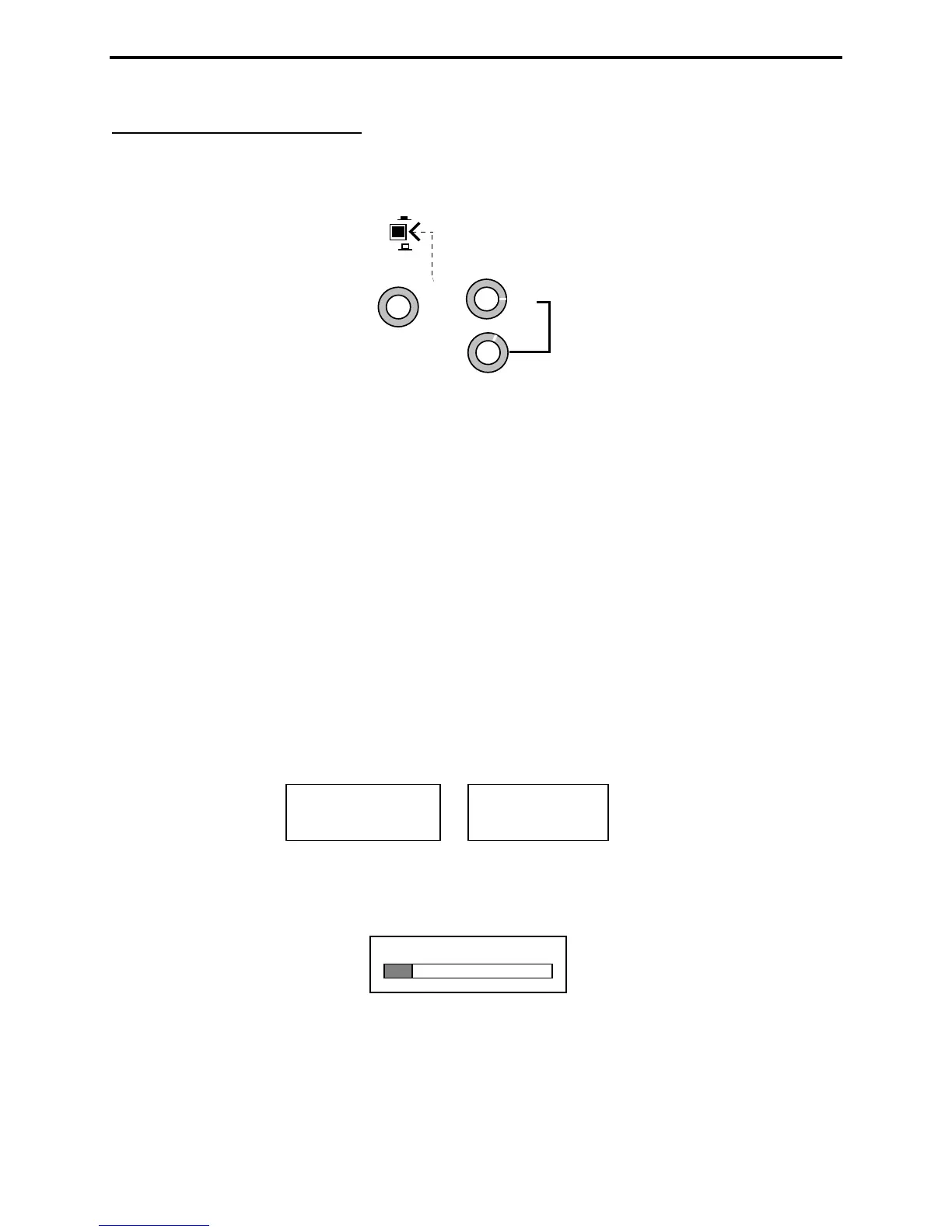
3.4 Frequency Control
The MFJ-269C tunable RF-oscillator covers an exceptionally wide frequency span, using two rotary band
switches for LF/HF/VHF coverage (.53-230 MHz) -- plus an additional pushbutton switch to activate
UHF coverage (415-470 MHz) .
155-230
113-155
67-113 28-67
11-28
4.7-11
2.1-4.7 1.0-2.1
0.53-1.0
Lower
Range
TUNE
FREQUENCY MHz
UHF
ON
OFF
UHF HI
UHF LO
1. LF, HF and VHF Operation: The Lower Range rotary switch selects four LF and HF bands (0.53-
11.0 MHz). The Upper Range switch selects 5 HF and VHF bands for 11-230 MHz coverage. Note that
the Upper Range switch must be set fully clockwise to the Lower Range position for the lower-range
band selector to function. The variable Tune control (VFO capacitor) provides a small overlap at each
band edge to ensure gap-free tuning across the spectrum.
*Note that LF coverage may be lowered to 0.47-0.94 MHz (or lower) for 600-Meters and select maritime
services. To modify, (1.) adjust Tune fully counter-clockwise, (2.) remove the back cover (3.) Remove
battery pack by removing Philips head screws and, (4.) using a 2-mm hex tuning wand, readjust inductor
L12 while watching the frequency display.
2. UHF Operation: UHF coverage is broken into two bands. To measure UHF SWR (415-490 MHz),
first press in the UHF switch located just above the LCD display. Then, for 415-470 MHz coverage, set
the upper Frequency MHz switch to the 113-155 MHz band (UHF LO). For 470-490 MHz coverage,
set the upper Frequency MHz switch to 155-230 MHz. (UHF HI).
It is normal for the VFO's Tune range to exceed the analyzer's usable UHF measurement range. If the
VFO frequency is out of range in UHF Mode, one of the error messages shown below will instruct you to
increase or decrease frequency to bring it back in range:
Adjust Tune clockwise to increase frequency and counterclockwise to decrease frequency. When in
range, the operating Frequency will appear on the top line of the LCD display -- along with the SWR
reading. The bottom display line becomes an analog SWR bar-graph (see below).
Remember to set the top Frequency MHz selector fully counterclockwise (155-230) when setting up for
UHF HI (470-490MHz) or set to the second to last switch position (113-155) when setting up for UHF
LO (415-470 MHz) measurements. The analyzer converts the analyzer's VHF oscillator up to the UHF
band for those measurements.
445.75 MHz 1.3
INCREASE
FREQUENCY
DECREASE
FREQUENCY