MFJ-269C Instruction Manual LF/HF/VHF/UHF SWR Analyzer
13
CAUTION: Only measure transformers or attenuators and coaxial cables that are 50-ohm devices. Also,
when making your measurement, confirm that the opposite end of the DUT (device under test) has an
open circuit, short circuit, or a purely reactive termination. Any resistive component added at the far-end
termination point will make attenuation (loss) appear worse than it actually is.
To measure loss:
1. Connect the 50-ohm cable, attenuator, transmission line type balun, or transformer under test to the
Antenna connector. Confirm the distant end of the DUT isn't terminated by a resistance.
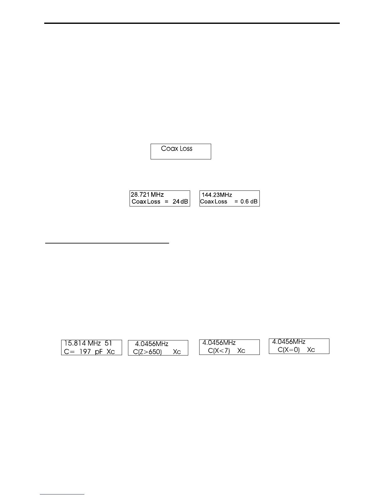
2. Turn the analyzer On and toggle the Mode switch once to the Coax Loss screen.
3. Tune the analyzer's VFO (Tune) to the frequency where you wish to measure loss. The loss in dB will
be displayed for any specific frequency you select between 0.53 and 230 MHz.
4.4 Capacitance (Function-3)
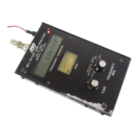
Access the capacitance mode by stepping to the Capacitance screen using the Mode switch. The top line
of the working display shows the Frequency in MHz and the Capacitive Reactance (Xc) of the DUT at
that specific frequency. The lower line displays the computed Capacitance in pF. Normally, the
measurement range is from a few pF to a few thousand pF.
Important Note: Capacitance measurements tend to become inaccurate below 7 ohms and above 650
ohms. If reactance falls into the inaccuracy range, C(X<7), C(X=0), or C(Z>650) will be displayed on the
screen as error messages. The MFJ-269C will not display "data" when the measurement accuracy is
questionable (see examples below):
Reactance Sign: The MFJ-269C measures the DUT's reactance (X) and mathematically converts it to a
capacitance value (Xc). However, the analyzer's processor can't determine if the reactance it measures is
actually capacitive or inductive. You can usually confirm the sign by simply adjusting the VFO. If tuning
down in frequency causes reactance to increase, the load is likely capacitive (-jX) because the reactance
of a capacitor normally increases with a decrease in frequency.
To measure a capacitor:
1. Turn on the analyzer and toggle the Mode switch twice to bring up the Capacitance identification
screen.