MFJ-269C Instruction Manual LF/HF/VHF/UHF SWR Analyzer
17
Advanced-2 Velocity Factor setup
(Section 5.5) Line length in degrees calculation
5.3 General Connections
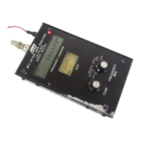
The Antenna connector (Type “N” female) on the top of the MFJ-269C provides the RF measurement
output connection. This port is used to measure SWR or perform other RF impedance measurements, with
the exception of the Frequency Counter mode.
The Antenna connector supplies about +7 dBm output into 50 ohms (~ .5 volts RMS), and appears like a
50 ohm source resistance (open circuit voltage ~1 volt RMS). Harmonics are at least 25 dB down over
the operating range of the MFJ-269C. While the VFO is not stabilized, it is useful as a crude signal
source.
The Antenna connector is not dc isolated from the load, external voltages will couple directly into
internal detectors.
WARNING: NEVER APPLY EXTERNAL VOLTAGES OR RF SIGNALS TO THE ANTENNA
CONNECTOR. ALSO, PROTECT THIS PORT FROM ESD.
Use proper RF connections. Keep leads as short as possible when measuring components or non-matched
systems. Interconnecting transmission lines or wires can modify readings, including impedance and
SWR. Use properly constructed coaxial cables of known quality matched to the analyzer impedance to
avoid introducing SWR errors.
5.4 Advanced -1 Modes
5.4.1 Advanced 1 (LF/HF/VHF)
Advanced-1 Mode measures impedance and SWR functions. To enter Advanced-1, press and hold down
the Mode and Gate buttons simultaneously for approximately two seconds.
Advanced 1
There are six display functions available within this mode (see list below):
Magnitude and phase of load impedance (5.4.1.1)
Series Equivalent impedance (5.4.1.2)
Parallel Equivalent impedance (5.4.1.3)
Return loss and Reflection coefficient (5.4.1.4)
Resonance (5.4.1.5)
Match efficiency (5.4.1.6)
To return to the Main (or Basic) menu, press and hold the Mode and Gate buttons to step through the
Advanced-2 and Advanced-3 screens.