MFJ-269C Instruction Manual LF/HF/VHF/UHF SWR Analyzer
23
5.5 Advanced- 2 Modes
This mode measures physical or electrical Distance To A Fault (such as a short, open, or large impedance
bump in a line). It also measures Electrical Length in degrees and calculates Wavelength in feet or meters.
To access Advanced-2, hold the Mode and Gate buttons until it appears on the display. You can also
reach it by stepping through the Advanced modes (hold Mode and Gate simultaneously until Advanced-
2 appears on the screen:
Advanced 2
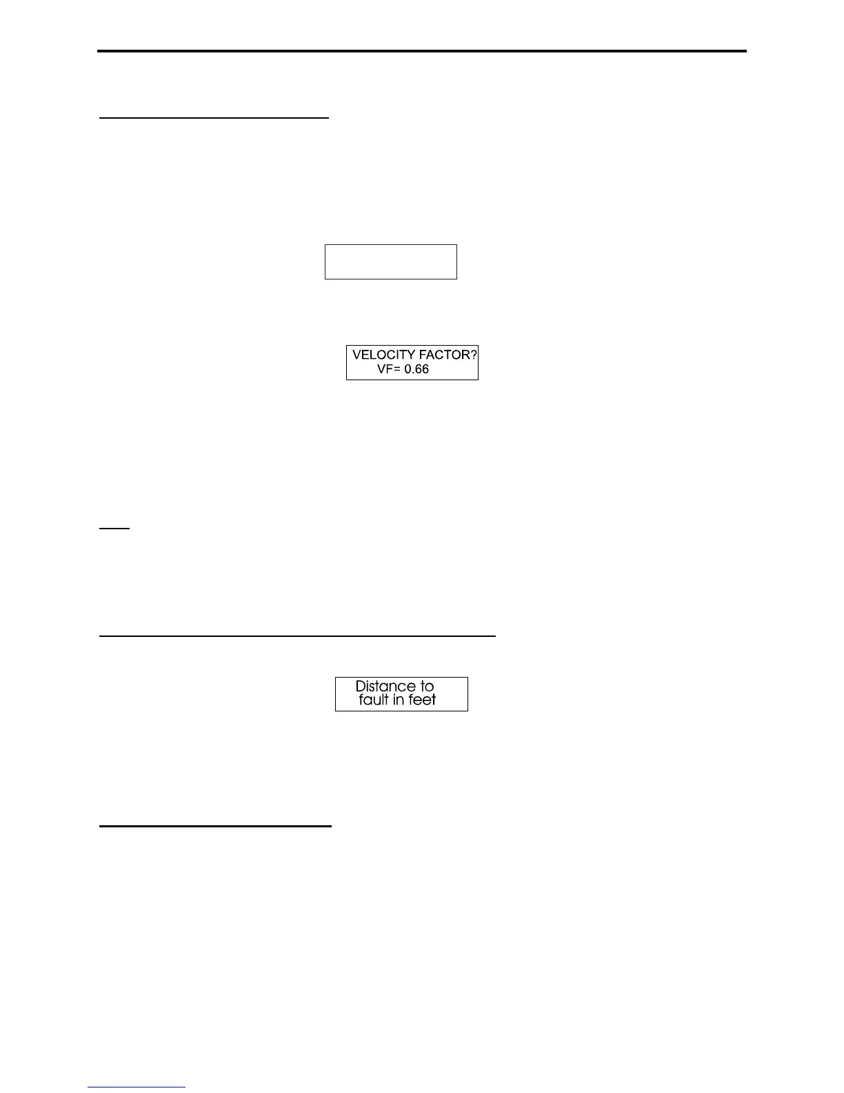
The opening measurement function in Advanced-2 is:
This prompt asks the operator to enter the factory-specified velocity factor for a cable being tested (DUT).
To increase velocity factor above the default of 0.66, press Gate. To decrease it, press Mode. When the
Vf value is correct, press both buttons simultaneously to lock the value in. The Vf entry is necessary for
determining the Physical Length of a line in feet. To obtain Electrical Length in feet, set Vf for unity
(1.00).
Note
: Incorrect Vf settings do not cause errors in electrical measurements such as Length in Degrees, but
do cause errors in physical length calculations such as Dist. to Fault displayed in feet. Note that
"distance" calculations aren't available at UHF frequencies because the internal capacitance of the diodes
and lead lengths through the connector and connections create errors in other measurements. Only SWR
and SWR related functions are displayed for the UHF band.
5.5.1 Distance to Fault (DTF) (for HF/VHF only)
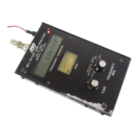
With Vf entered in the previous function, the next function in the display menu is:
Distance to Fault in Feet measures any line type (or impedance), including the length of a Beverage or
other antenna (any terminations must be removed). Section 5.5.1.4 outlines the measurement procedures,
or "how" to measure something. Sections 5.5.1.1 through 5.5.1.3 describe a few practical things that can
be measured.
5.5.1.1 DTF Balanced Lines
Line placement is critical when measuring balanced line and the MFJ-269C must run on internal batteries
to maintain isolation. Also, you must keep the case a few feet away from other conductors and earth. No
wires (other than the balanced line) can be attached. Use the Antenna connector’s shield for one lead and
the center pin for the other. Two wire balanced lines must be suspended in a reasonably straight line and
held at least a few feet away from other objects using good insulators. Avoid laying the line against
anything -- including non-conductors -- for any distance, and keep it several conductor spacings away
from other conductive surfaces (even poor conductors like earth or concrete).