MFJ-998 Legal Limit IntelliTuner Automatic Antenna Tuner Instruction Manual
© 2007-2010 MFJ Enterprises, Inc.
11
The MFJ-5114K interface provides control signals between a Kenwood radio and the MFJ automatic
tuner. Supported Kenwood radios are TS-50S, TS-450S, TS-480HX, TS-570S, TS-690S, TS-850S,
TS-870S, TS-2000, and any Kenwood radio that supports the Kenwood AT-300 tuner. Push and hold
the radio’s [AT TUNE] button for one second to start the tuning process. Push the [AT TUNE]
quickly to bypass the tuner or to cancel tuning in progress. Make sure jumper JP1 is installed. Refer
to “Kenwood Radio Interface” on page 34 for connections and operation.
Note: The TS-480HX will automatically reduce its TX power to 100 watts maximum (25 watts
AM) when the radio interface is used.
Note: For the TS-2000, use the ANT 1 and AT connectors on the radio to connect an external
antenna tuner. If the external tuner is connected to the ANT 2 connector on the radio, the
external tuner will not function with the radio interface.
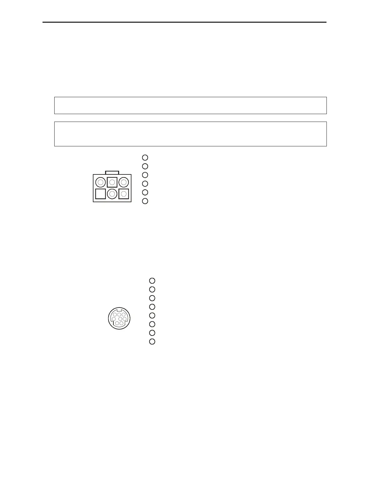
Pin 1 (Ground) connects to pin of Radio Interface Plug.
Pin 2 (TT) connects to pin 6 of Radio Interface Plu
Pin (Ground) connects to pin 5 of Radio Interface Plug.
Pin 5 (TS) connects to pin 8 of Radio Interface Plug.
g.
3
Pin 4 is not connected.
Pin 6 (+13.8V) connects to pins 2 and 3 of Radio Interface Plug.
4
1
3
2
4
65
Kenwood
Rear Panel View
1
2
3
4
5
6
Figure 8. Kenwood Interface Cable.
The MFJ-5114Y interface provides control signals between a Yaesu radio and the MFJ automatic
tuner. Supported Yaesu radios are FT-100, FT-450, FT-857, FT-897, FT-950, and any Yaesu radio
that supports the Yaesu FC-30 tuner. Push and hold the radio’s (TUN) or (TUNE) key to start the
tuning process. Make sure jumper JP1 is installed. Refer to “Yaesu Radio Interface/MFJ-5114Y” on
pages 35 to 38 for connections and operation.
(TX INH) connects to pin 7 of Radio Interface Plug.
(SENSE) connects to pin 5 of Radio Interface Plug.
g.
RX
Pin 8 (+13.8V) connects to pin 3 of Radio Interface Plug.
Pin 2 is not connected.
Pin 3
Pin 4 (TX) connects to pin 6 of Radio Interface Plu
Pin 5 ( ) connects to pin 8 of Radio Interface Plug.
Pin 6 (Ground) connects to pin 4 of Radio Interface Plug.
Pin 7 is not connected.
Pin 1
123
456
78
Yaesu
Rear Panel View
1
2
3
4
5
6
7
8
Figure 9. Yaesu Interface Cable (FT-100/-450/-857/-897/-950).
The MFJ-5114Y3 interface provides control signals between a Yaesu radio and the MFJ automatic
tuner. Supported Yaesu radios are FT-1000MP, FT-1000MP MKV, FT-1000MP MKV Field, FT-
2000, FT
DX-9000, and any Yaesu radio compatible with the Yaesu FH-1 or FH-2 Remote Control.
This cable plugs into the REMOTE jack on the rear panel of the Yaesu radios, and keys the Yaesu
radios in the CW tune mode whenever the MFJ-998’s [TUNE] button is pushed. MFJ recommends
that the Yaesu CW tune setting be set to 10 watts (Yaesu MP menu selection 4-3) during the tune
process when an amplifier is not used. For best accuracy when an amplifier is used, MFJ
recommends that the Yaesu CW tune setting be set to 50 watts for 100-watt transceivers and 75 watts

 Loading...