MFJ-998 Legal Limit IntelliTuner Automatic Antenna Tuner Instruction Manual
© 2007-2010 MFJ Enterprises, Inc.
12
for 200-watt MKV transceivers during the tune process. If a FH-1 or FH-2 keypad is also used, both
the FH-1/FH-2 and the radio control cable may be plugged in parallel using a 3.5-mm headphone
splitter (mono or stereo is fine). Refer to “Yaesu Radio Interface/MFJ-5114Y3” on page 39 for
connections and operation.
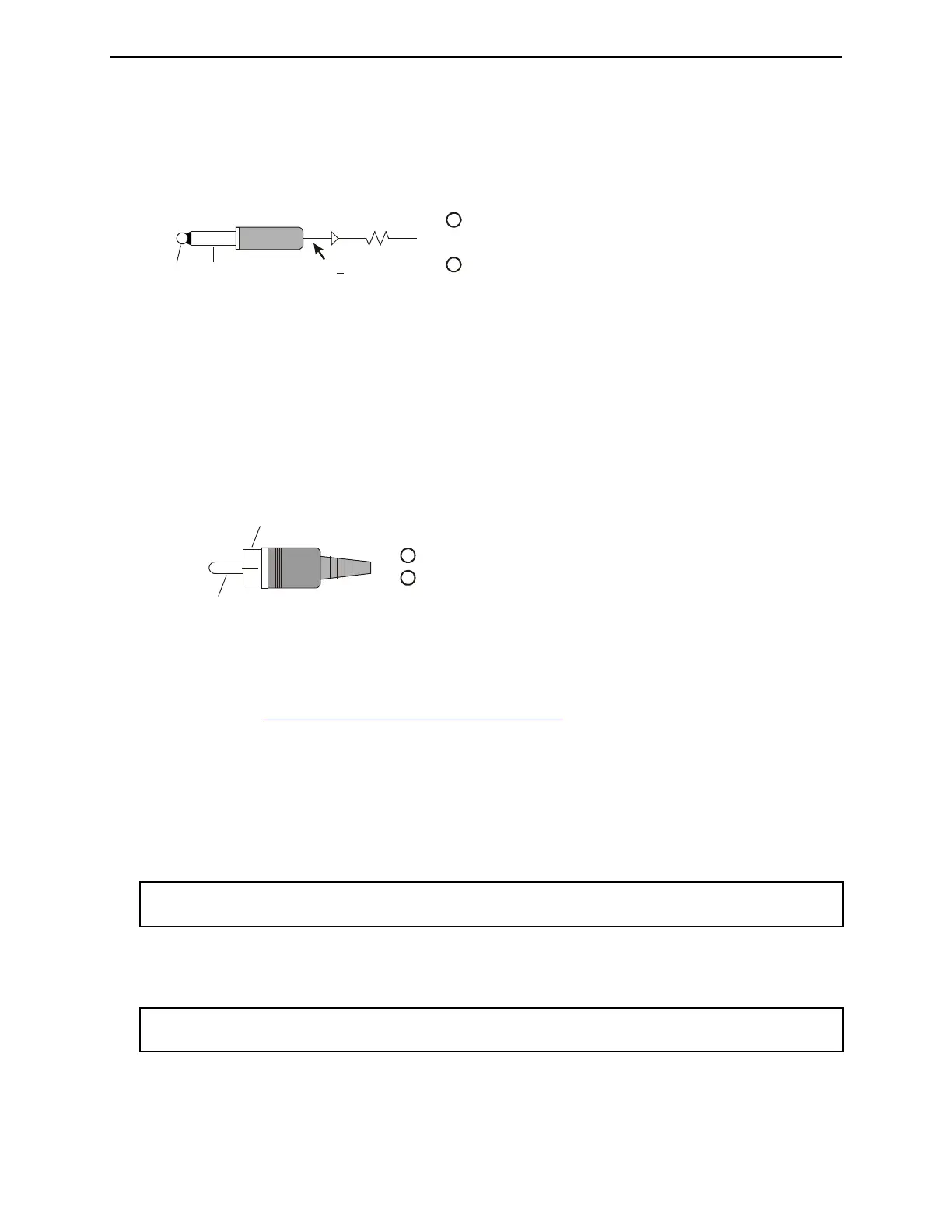
Tip (KEY) connects to pin 6 of Radio Interface Plu
Sleeve (GND) connects to pins 4 and of Radio Interface Plug.
with a diode and a 22.1k ohm 1% resistor in series.
5
g
1
2
KEY GND
22.1K1N4148
4.2V + 0.13V
Figure 10. Yaesu Interface Cable (MP/2000/9000 series).
While the MFJ-5114Y3 works with the FT-2000, the FT-2000 also has a TX REQ input that can be
used. If you prefer to use the TX REQ input, the MFJ-5114Y4 interface provides control signals
between the Yaesu FT-2000 and FT-2000D radios and the MFJ automatic tuner. This cable plugs
into the TX REQ RCA jack on the rear panel of these Yaesu radios, and keys the Yaesu radios in the
CW tune mode whenever the MFJ-998’s [TUNE] button is pushed. MFJ recommends that the Yaesu
tune power setting be set to 20 watts (Yaesu menu 145 tGEn TUN PWR) during the tune process.
Refer to “Yaesu Radio Interface/MFJ-5114Y4” on page 41 for connections and operation.
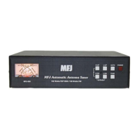
Center pin (KEY) connects to pin 6 of Radio Interface Plu
Ground (GND) connects to pins 4 and of Radio Interface Plug.5
g.
1
2
KEY
GND
Figure 11. Yaesu Interface Cable (FT-2000 series).
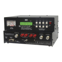
• Serial Port: DB-9 female connector for connecting to the computer’s RS-232 serial port to update
firmware. Check http://www.mfjenterprises.com/support.php
for the latest version of the firmware.
• Transmitter: SO-239 connector for coax cable from transceiver or amplifier.
• Ground: Wing-nut terminal for RF ground wire connection.
• Wire: Binding post for connecting single wire antenna. The WIRE binding post is internally
connected to the ANTENNA 1 connector.
Note: When using the WIRE binding post, there should be no coax cable connected to the
ANTENNA 1 connector.
• Antenna 1: SO-239 connector for coax cable from antenna. The ANTENNA 1 connector is
internally connected to the WIRE binding post.
Note: When using the ANTENNA 1 connector, there should be no wire attached to the WIRE
binding post.
• Antenna 2: SO-239 connector for coax cable from antenna.