Home
Michell Instruments
Measuring Instruments
Cermet II
Michell Instruments Cermet II User Manual
4
of 1
of 1 rating
52 pages
Give review
Manual
Specs
To Next Page
To Next Page
To Previous Page
To Previous Page
Loading...
Cermet II User’s Manual
4
97049 Issue 25.3, October 2016
INSTALLATION
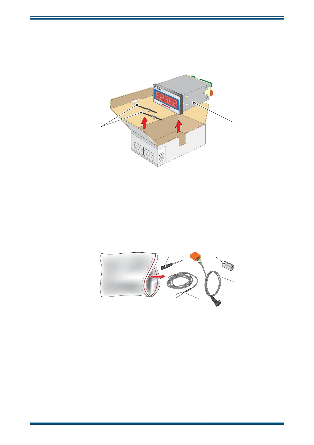
2.1.2
Unpacking the Cermet II Monitor
The monitor (2) is packed, together with its
fi
xing clamps (1) as shown below.
1
°C
dp
°F
dp
Cermet II
Advanced Online
©
ª
Setup
2
Figure 3
Unpacking - Monitor
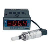
2.1.3 Accessories
Pack
The accessories pack is shown below:
1
2
3
4
Figure 4
Unpacking - Accessories P
ack
10
12
Table of Contents
Default Chapter
4
Table of Contents
4
Safety
6
Electrical Safety
6
Pressure Safety
6
Toxic Materials
6
Repair and Maintenance
6
Calibration
6
Safety Conformity
6
Abbreviations
7
Warnings
7
1 Introduction
8
Features
8
2 Installation
9
Unpacking the Instrument
9
Figure 1 Unpacking - Monitor and Accessories
9
Unpacking the Cermet II Transmitter
10
Figure 2 Transmitter Unpacking Method
10
Unpacking the Cermet II Monitor
11
Accessories Pack
11
Figure 3 Unpacking - Monitor
11
Figure 4 Unpacking - Accessories Pack
11
Cermet II Components
12
Figure 5 Components
12
Monitor
13
Monitor Panel Layout
13
Figure 6 Control Layout and Functions
13
Preparation of the Transmitter Cable
14
Figure 7 Connector Terminal Block Removal
14
Transmitter Mounting
15
Transmitter Mounting - Sample Block and Gas Connections (Optional)
16
Figure 8 Sample Block Gas Connections
16
Figure 9 Transmitter Mounting - Sensor Block
17
Transmitter Mounting - Direct Pipeline Connection
18
Figure 10 Transmitter Mounting - Pipe or Duct
18
Transmitter Mounting - with Additional Process Connection Adapter
19
Figure 11 Transmitter Mounting with Adapter
19
Monitor Mounting
20
Figure 12 Mounting the Monitor
20
Electrical Connections
21
High Voltage Power Supply Input
21
Figure 13 High Voltage Power Supply Connections
21
Low Voltage Power Supply Input
22
Pressure Transducer Connection (Optional)
22
Figure 14 Low Voltage Power Supply Connections
22
Figure 15 Electrical Connection Detail
22
Transmitter Cable Connection
23
Figure 16 Cable Connections
23
Figure 17 Connector Installation
23
Table 1 Cable Connections
23
3 Operation - Monitor
24
Set-Up Security Feature
24
Figure 18 Location of the Lockout Switches
24
Table 2 Operation Access Levels
24
Selecting the Engineering Units
25
Changing the Setpoint Values
25
Hysteresis, Make/Break Delay & Delay Type
26
Analog Output Scaling
26
Display Brightness Adjustment
27
Digital Communications
27
Pressure Compensation
28
Using a Pressure Transducer
28
Manual Pressure Input Calibration
29
Automatic Pressure Input Calibration
29
Using a Fixed Pressure Input in Single Channel Mode
30
4 Operation - Transmitter
31
Figure 19 Installation Location
31
Figure 20 Indication of Dead Space
31
5 Maintenance
32
Figure 21 Replacement of HDPE Guard
32
Appendix A Technical Specifi Cations
34
Appendix A Technical Specifi Cations
37
Appendix B Setup Codes
37
Appendix C Register Settings Accessible by Digital Communication
40
Appendix Deu Declaration of Conformity
43
Appendix E Quality, Recycling & Warranty Information
45
Pressure Equipment Directive (PED) 97/23/EC
45
Recycling Policy
45
WEEE Compliance
45
Rohs2 Compliance
46
Warranty
46
REACH Compliance
47
Return Policy
47
Calibration Facilities
48
Manufacturing Quality
48
FCC (EMC Requirements for North America)
48
Appendix F Return Document & Decontamination Declaration
50
4
Based on 1 rating
Ask a question
Give review
Questions and Answers:
Need help?
Do you have a question about the Michell Instruments Cermet II and is the answer not in the manual?
Ask a question
Michell Instruments Cermet II Specifications
General
Brand
Michell Instruments
Model
Cermet II
Category
Measuring Instruments
Language
English
Related product manuals
Michell Instruments PC33
28 pages
Michell Instruments Optidew
96 pages