Cermet II User’s Manual
10 97049 Issue 25.3, October 2016
INSTALLATION
7. Push the stainless steel tubing (1) as far as it will go into the adaptor (5)
and tighten up the locking nut (2) fi nger tight.
8. Hold the adaptor (5) fl ats with a spanner and tighten up the locking
nut (2) to a torque setting of 35 Nm (25 lbf-ft) (1¼ turns). This action
compresses the front ferrule (4) and back ferrule (3) onto the tubing to
form a gas tight seal.
9. Connect up the other gas port as described in steps 1 to 8 above.
The following procedure must be carried out by a
qualifi ed installation engineer.
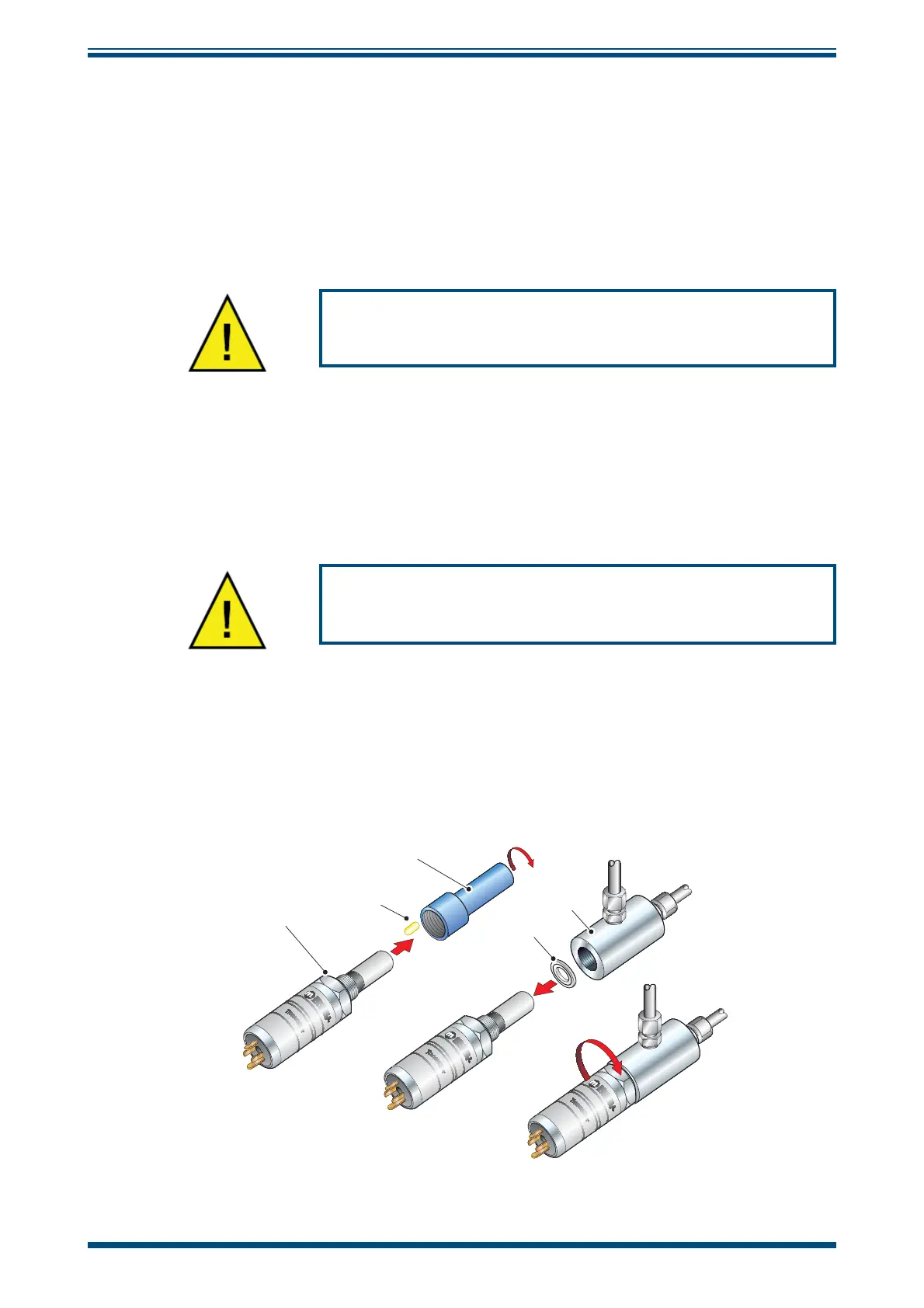
To mount the transmitter into the sample block (preferred method), proceed as follows,
refer to
Figure 9.
1. Remove the blue protective cover (2) and its desiccant capsule (2a), from
the tip of the transmitter.
2. Fit the bonded seal (3) over the threaded part of the transmitter body.
WARNING: Under no circumstances should the sensor
guard be handled with the fi ngers.
3. Screw the transmitter (1) into the sample block (4) and tighten to a
minimum torque setting of 30.5 Nm (22.5 ft-lbs). NOTE: Use the fl ats
of the hexagonal nut and not the transmitter body.
4. Fit the transmitter cable/connector assembly to the plug located on the
base of the transmitter and tighten the fi xing screw (see Section 2.10).
1
2
3
2a
4
Figure 9
Transmitter Mounting - Sensor Block