Cermet II User’s Manual
16 97049 Issue 25.3, October 2016
INSTALLATION
2.10 Transmitter Cable Connection
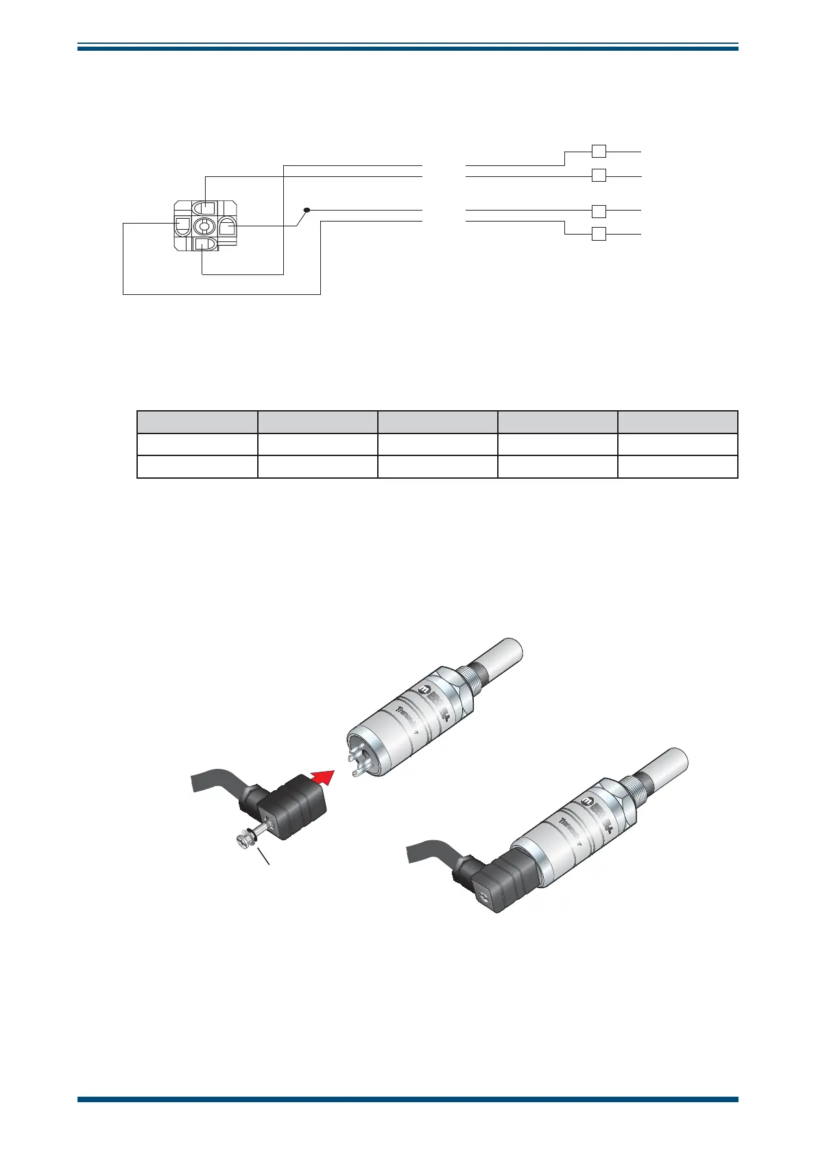
The diagram below shows the identity of the connector terminals.
YELLOW
GREEN
BLUE
RED
PIN 3
PIN 2
RED
+Power
YELLOW
Signal (A)
GREEN
Signal (B)
PIN 1
BLUE
Ground
1
2
3
4
YELLOW Signal (A)
BLUE Ground
GREEN Signal (B)
RED +Power
Figure 16
Cable Connections
The transmitter cable connections are shown in the table below and in the fi gure above.
Connection Red wire Blue wire Green wire Yellow wire
Monitor Pin 1 Pin 2 Pin 3 Pin 4
Transmitter Pin 3 GND Pin 1 Pin 2
Table 1 Cable Connections
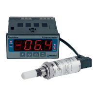
When installing the connector, and to ensure that full ingress protection is achieved, the
securing screw (with the O-ring and washer) must be tightened to a minimum torque
setting of 3.4 Nm (2.5 ft-lbs). The transmitter cable used must be a minimum diameter
of 4.6mm (0.2”).
O-ring
and washer
i
Figure 17
Connector Installation