Page 29
induSENSOR, EDS
4.4.2 Model EDS- ... -F
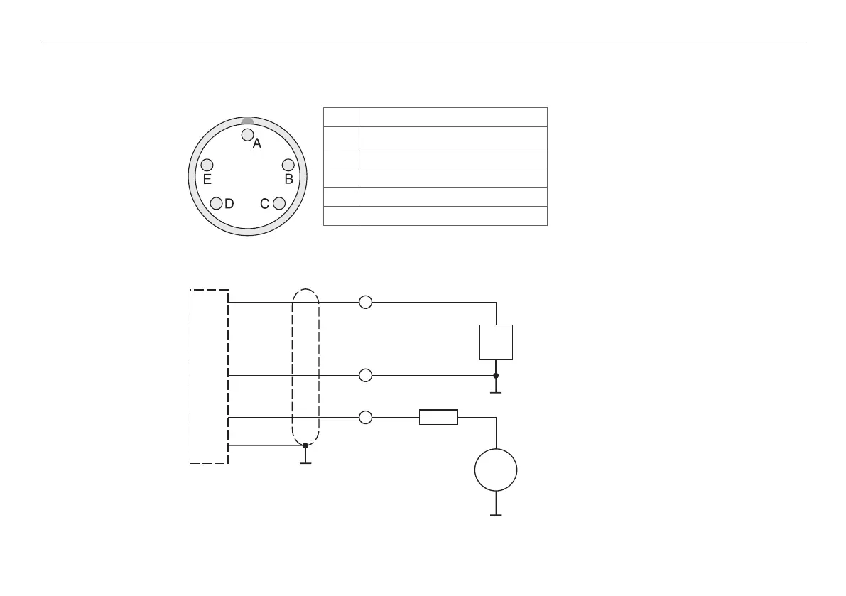
Power supply and signal output are effected through the 5-contact connector on the sensor’s electronic
housing. The pin assignment is shown, see Fig. 22.
Pin Assignment A 5-pin cable socket for the user-side as-
sembly of your own connecting cable is
part of the delivery scope.
A Power supply + (18 ... 30 VDC)
B Ground
C 4 ... 20 mA
D Housing
Fig. 22 Table connection pin assignment,
bayonet connection, view of solder pin
side female cable connector
E ---
+
_
+
_
18...30 VDC
I
R
U
B
A
L
OUT
B
C
A
D
E
EDS-...-F
R
L
can be inserted as an option for adap-
tation of the power loss to high ambient
temperatures, see Chap. 4.4.4.
Fig. 23 Signal monitoring with ampere-
meter
Connector
Type CA02COM-G14S
The C705-5 sensor
cable is available as an
accessory.