Page 30
induSENSOR, EDS
+
_
+
18...30 VDC
U
B
U
V
R
L
OUT
I
S
B
C
A
D
E
EDS-...-F
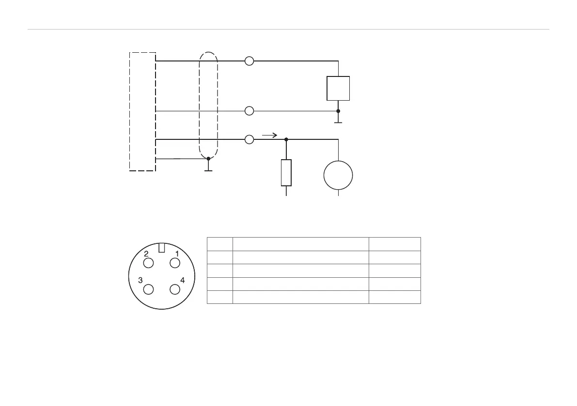
If the signal is monitored with a voltmeter
the load resistor R
L
is dimensioned in ac-
cordance with the desired output voltage
U
OUT
.
Formula: U
OUT
= R
L
* I
Signal
Fig. 24 Signal monitoring with load resis-
tor and voltmeter
4.4.3 Model EDS-...-Z
Power supply and signal output are effected through the 4-contact connector on the hydraulic cylinder. The
pin assignment is shown, see Fig. 25.
Pin Assignment Color A 4-pin cable socket for the
user-side assembly of your
own connecting cable is
part of the delivery scope.
Fig. 25 Connection pin
assignment, view of solder
pin side female cable con-
nector
1 Signal ground brown
2 Power supply + (18 ... 30 VDC) white
3 Signal (4 ... 20 mA) blue
4 Supply ground black