Page 27
induSENSOR, EDS
4.4 Power Supply and Display/Output Device
4.4.1 Model EDS- ... -S
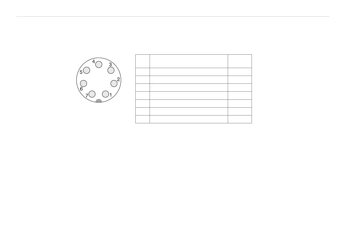
The power supply and the signal output are effected through 7-pin connector on the sensor’s electronic
housing. The pin assignment is shown, see Fig. 19.
View on solder pin
side, female cable
connector
Fig. 18 Binder con-
nector Type 702
Pin Assignment Color
C703-5
Pin 2 is connected with
pin 4 on the electronics
board. The screen of the
sensor cable is connected
with the connector hous-
ing. Connect the screen of
the sensor cable with the
protective earth conductor
on power side.
1 Power supply +
(18 ... 30 VDC) white
2 0 V Ground brown
3 I
OUT
4 ... 20 mA
1
green
4 Signal ground yellow
5 SCL (Sensor calibration) grey
6 SCL (Sensor calibration) pink
7 n.c. blue
Fig. 19 Connection pin assignment, 7-pole
The sensor cable C703-5 and C704-5, length 5 m, are available as an accessory.
1) Output voltage of 1 up to 5 V with the C703-5/U supply and output cable.