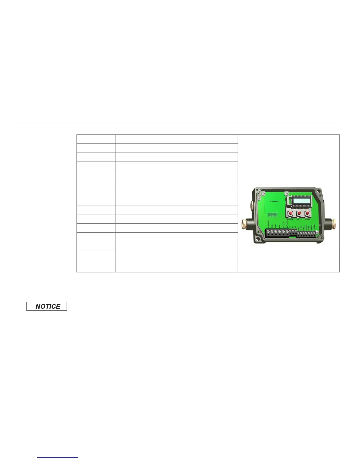
7.1.1.2 CTM-1, CTM-2, CTM-3 Models
PIN Designation
+8 ... 36 VDC Power supply
GND Ground (0 V) of power supply
GND Ground (0 V) of internal in- and outputs
AL2 Alarm 2 (Open collector output)
OUT-TC Analog output thermocouple (J or K)
OUT-mV/mA Analog output object temperature (mV or mA)
F1-F3 Functional inputs
GND Ground (0 V)
3V SW 3 VDC, switchable, for laser sighting tool
GND Ground (0 V) for laser sighting tool
BROWN BROWN/temperature probe sensor (NTC)
WHITE WHITE/sensor ground
GREEN GREEN/sensor power Fig. 32 Opened controller
(CTM-1, CTM-2, CTM-3) with terminal
connections
YELLOW YELLOW/detector signal
7.2 Power Supply
Please use a power supply unit with an output voltage of 8 – 36 VDC/100 mA. The ripple should be
max. 200 mV.
Please do never connect a supply voltage to the analog outputs.
> Destruction of the output
The thermoMETER CT is not a 2-wire sensor!