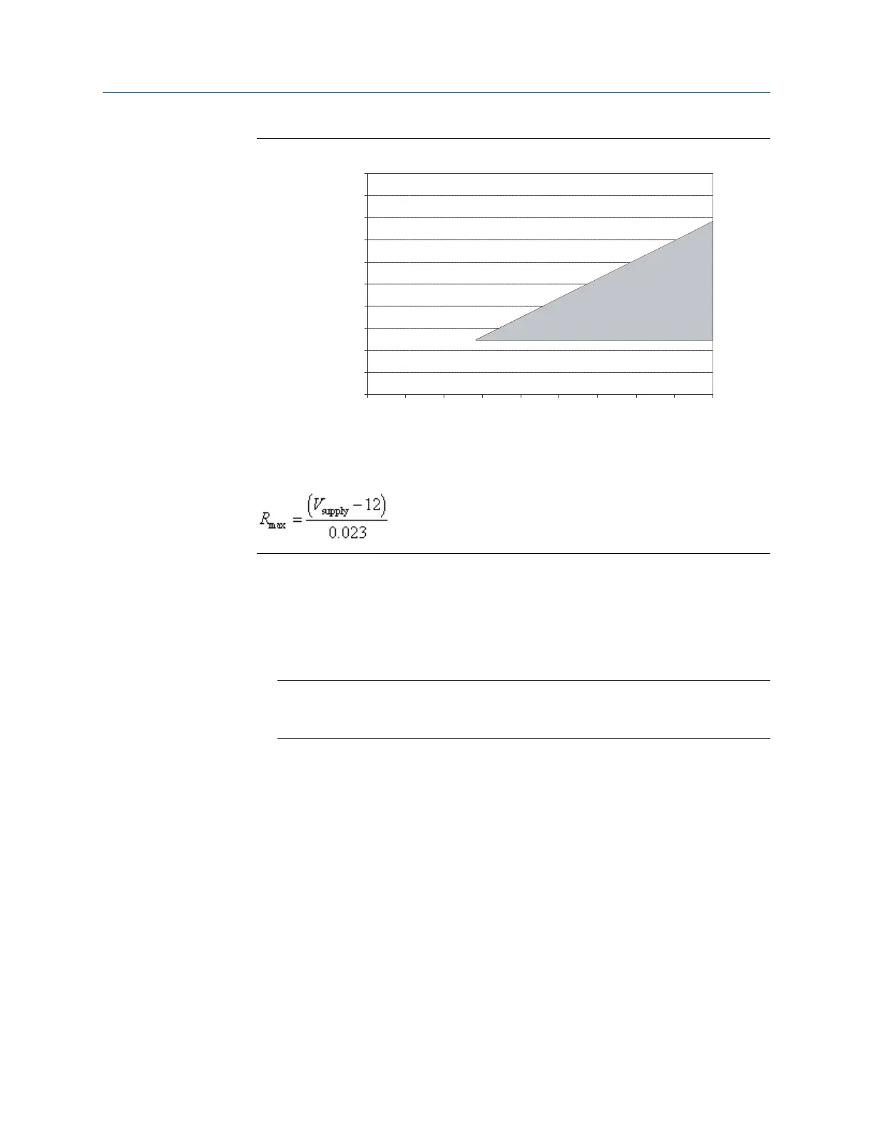
Supply voltage and resistance requirementsFigure C-4:
900
1000
700
800
600
500
400
300
100
200
0
12 14 16 18 20 22 24 26 28 30
Supply voltage VDC (volts)
Operating range
External resistance (Ohms)
Note
3. To connect to a point in the local HART loop:
a. Attach the leads from the signal converter to any point in the loop, ensuring that
the leads are across the resistor.
b. Add resistance as necessary.
Important
HART/Bell 202 connections require a voltage drop of 1 VDC. To achieve this, add
resistance of 250–600 Ω to the connection.
Using ProLink III with the transmitter
Configuration and Use Manual 197