Installation (cont.)
Trak-Star Ultrasonic Speed Sensor (cont.)
Installation (cont.)
3. Plug adapter cable into connector on Trak-Star and
permanently mount sensor with flat washers, lockwashers
and hex nuts. The blue wire on the Trak-Star cable and
MT-3000/5000 adapter cable must be attached to the
frame making sure there is good metal to metal contact.
The wires may be attached to one of the mounting bolts
or any other convenient screw or bolt. Cut blue wires to
appropriate length and attach ring terminals provided.
4. Remove backing from decals provided and place
over unused mounting channels to prevent dirt
accumulation.
5. Run the adapter cable to the control console’s speed
sensor cable, avoiding other electrical wiring and areas
of high heat or abrasion. Secure cable along entire
length with cable ties. DO NOT plug cables together
until calibration is complete.
NOTE: See calibration information on the next page for
additional calibration information.
Adapter Cables
By substituting the appropriate cable for the MT-3000/5000
cable supplied, the Trak-Star ultrasonic speed sensor may
also be used with a variety of other makes and models of
controllers and monitors including: Micro-Trak, Calc-An-
Acre, Flow-Trak, Yield-Trak, Dickey-john, Gandy DAS, Hiniker,
Magnavox, Raven and SED/Field Electronics.
GENERAL INFORMATION
1. All adapter cables are equipped with a six pin connector
for direct connection to the Trak-Star and an appropriate
mating connector on the other end to plug into the
monitor/controllers standard speed input cable.
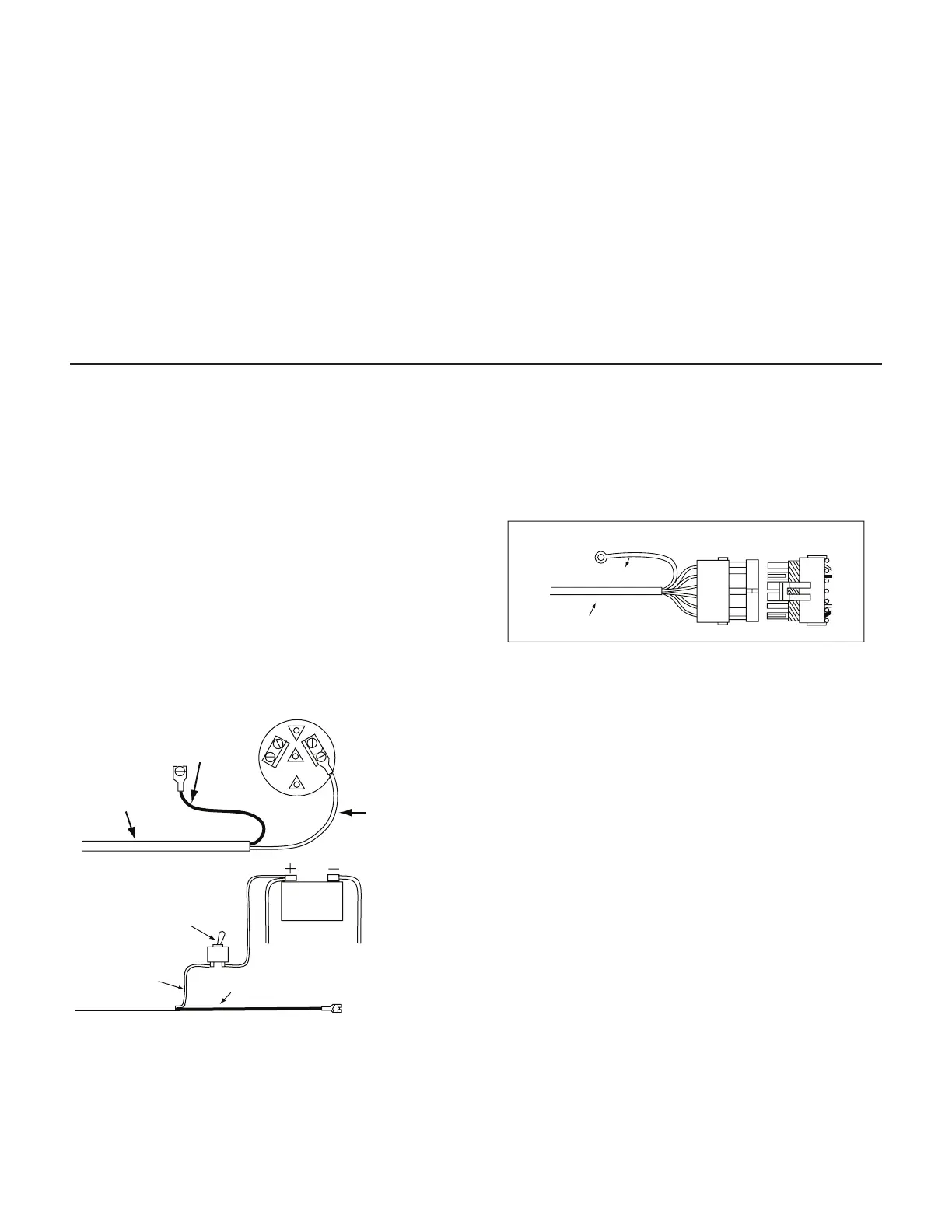
2. The adapter cables for units which do not provide a
power source for the speed sensor have an attached tow
conductor power card which must be connected to the
tractor or vehicles’s 12 VDC power system.
BLACK WIRE
TO FRAME (GROUND)
POWER CORD
RED WIRE TO
TERMINAL OR
LEAD WIRE
THAT IS “HOT”
WITH IGNITION ON
ON/OFF
POWER SWITCH
12 VDC
BATTERY
RED WIRE
BLACK WIRE TO FRAME (GROUND)
Cut power cord to appropriate length and strip 3/8” (1 cm)
of insulation from the end of each wire and attach spade
terminals provided (or other connectors is desired).
3. In all cases the blue wire from the Trak-Star must be
attached to the equipment frame (ground).
NOTE: GROUND CONNECTION (ALL UNITS)
BLUE WIRE TO FRAME (GROUND)
TRAK-STAR CABLE
14
Care and Maintenance
1. Always cover or remove the Trak-Star before traveling at
highway speeds. Flying rocks, road sand and bugs can
damage the transmitter/receiver. Physical damage IS
NOT covered by the factory warranty.
2. Trak-Star’s case is watertight under normal weather
conditions and washing. However, do not subject the
unit to steam or pressure cleaning.
3. Keep the transmitter horn free of dirt and mud. The horn
should be cleaned with low pressure water or an aerosol
automotive brake cleaner or electronic contact cleaner.
DO NOT use base ph liquids on horn. DO NOT insert
screwdrivers or other sharp objects into the horn.
4. When cable are disconnected, plug in the protective end
caps to prevent dirt or water from entering the connectors
which may result in corrosion or poor contact.
5. Nicks or cuts in cable insulation should be immediately
sealed or repaired to prevent corrosion to the wire or
short circuits.
6. If an arc welder or any other source of high voltage will
be used on the tractor or implement, disconnect all
ground and power to prevent damage to the electronic.