Troubleshooting (cont.)
Checking Individual Components
29
CONSOLE
The only way to field test a console is to connect it to a
harness on a vehicle with a known working MT-3000 system
or install it on an EPOP (electronic point of purchase) display
stand. NEVER try to direct wire the connector of an MT-3000
console.
HARNESS
The main harness can be checked using a DC Volt Meter
or test light. Unplug the main harness from the console.
Disconnect all three-pin connectors (speed, flow, remote
run/hold, servo and boom solenoids). Connect all power
wires . See page 11.
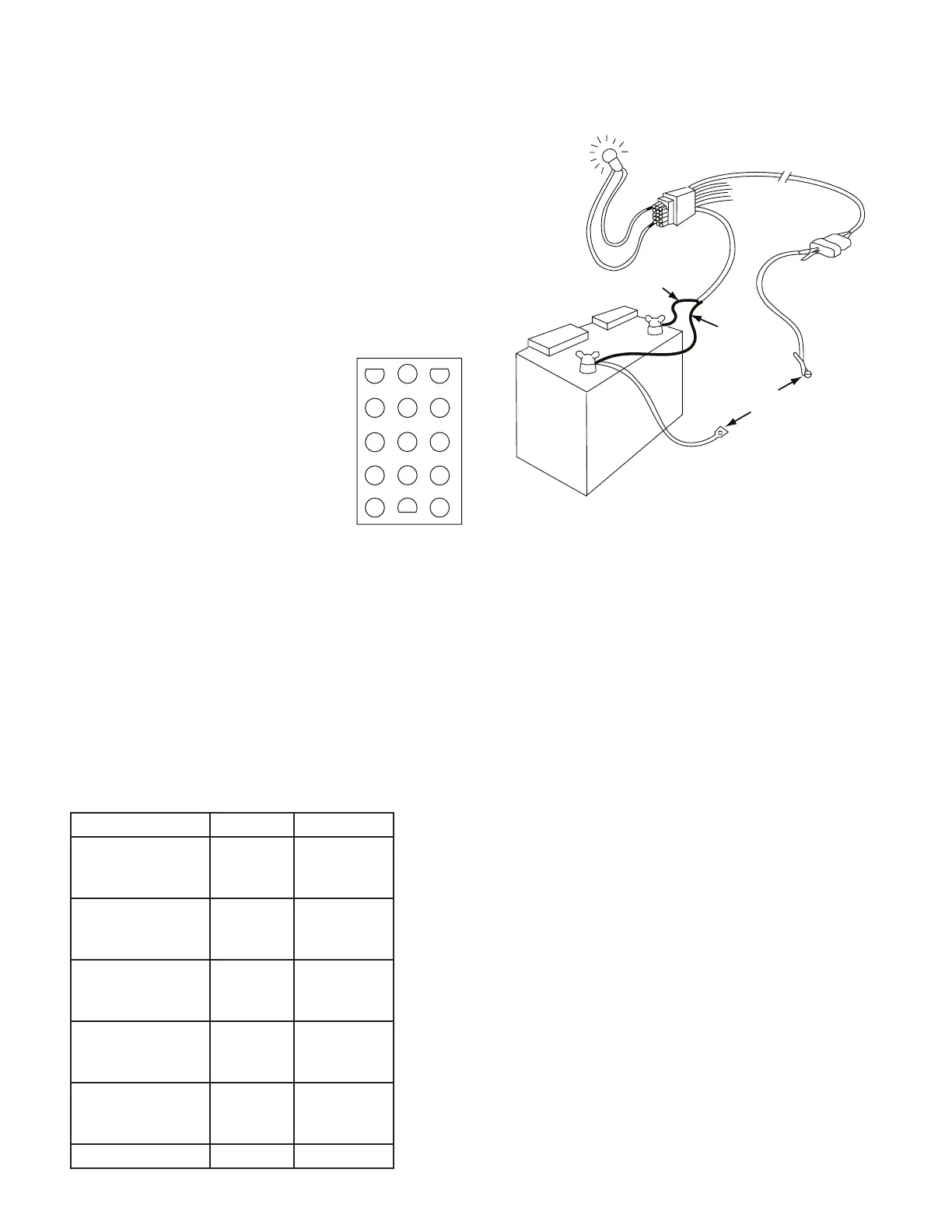
Connect one test probe to a good frame
ground. Touch the other test probe to
pin 13 of the harness connection. See
Illustration to the right. Power should be
present (meter reads about 12 V or test
light lights.). If no power, check the large
orange wire to battery. Now touch one
probe to pin 13 and the other to pin 7.
If no power, check the large blue wire to
the battery.
Now touch one probe to pin 10 and the other to pin 7. Power
should be present when the ignition switch is turned on. If
not, check the small orange power wire.
To test the rest of the harness, use a clip lead or other jumper
wire to ground the pin indicated by the following chart.
Connect one test probe to pin 13 and touch the other probe
to all the other pins one at a time. The chart shown which
ones should have power. If too many pins have power, there
is a short in the harness. If the indicated pins do not have
power, there is a poor connection at the large orange battery
wire, or the grounding jumper, or a break in the harness.
There should always be power between pions 13 and 7.
ELECTRICAL INTERFERENCE
Erratic operation may be a result of electrical interference
from ignition wires or inductive loads (electric clutch, fan,
solenoid, etc.). You may need to relocate the console and/or
wiring or install noise suppressor and/or resistor spark plugs
or wires.
ACCESSORY POWER
The white wire of the main harness speed, flow and remote
Run Hold cables supplies 12 volt power to optional accessories
such as the Trak-Star Ultrasonic Speed Sensor. If this wire
shorts to ground, the console’s thermal overload will trip and
shut down the entire MT-3000 system. Remove the short
and turn power off for 30 seconds to reset.
INPUTS
Provided the main harness checks out OK, the console’s
speed and flow inputs can be checked fa follows:
• If checking speed, turn to speed and disconnect the
speed sensor (yellow tie).
• If checking flow, turn to flow rate and disconnect the
flow sensor (green tie).
Then using a clip lead or other jumper wire (paper clip bent
in a “U”) short together several time rapidly. The two outside
pins of the appropriate connector of the main harness are
OK. If the monitor does not respond, the monitor or the main
harness is defective.
1 2 3
4 5 6
7 8 9
10 11 12
13 14 15
PINS 1, 3 & 14
POWER FROM
PIN 13 TO PIN
INDICATED BY
CHART TO RIGHT
12 VOLT
TEST LIGHT
SHOULD LIGHT
GROUND THE
WIRE INDICATED
BY THE CHART
ORANGE
BLUE
GROUND
Ground this Pin Wire Color Power at Pin
Remote Run/Hold
(Shortest Cable)
Red
White
Black
1
4
2
Speed Input
(Yellow Tie)
Red
White
Black
8
4
2
Flow Input
(Green Tie)
Red
White
Black
5
4
2
Boom Solenoids
(Black Tie)
Red
White
Black
12
9
6
Servo Valve
(Reversed Connector)
Red
White
Black
15
11
14
Small Brown Wire 3