MPLAB
®
ICD 4 User’s Guide
DS50002596A-page 22 2017 Microchip Technology Inc.
2.3.4 Circuits That Will Prevent the Debugger From Functioning
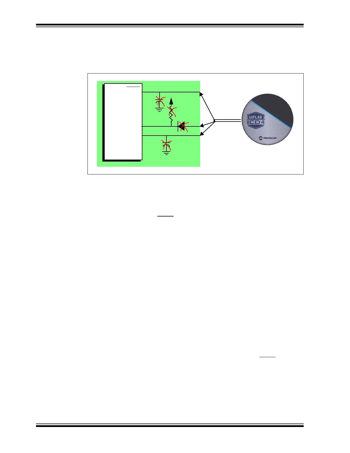
Figure 2-5 shows the active debugger lines with some components that will prevent the
MPLAB ICD 4 In-Circuit Debugger system from functioning.
FIGURE 2-5: IMPROPER CIRCUIT COMPONENTS
In particular, these guidelines must be followed:
• Do not use pull-ups on PGC/PGD – they could disrupt the voltage levels.
• Do not use capacitors on PGC/PGD – they will prevent fast transitions on data
and clock lines during programming and debugging communications, and slow
programming times.
• Do not use capacitors on MCLR
– they will prevent fast transitions of VPP. A
simple pull-up resistor is generally sufficient.
• Do not use diodes on PGC/PGD – they will prevent bidirectional communication
between the debugger and the target device.
2.4 DEBUGGING
There are two steps to using the MPLAB ICD 4 In-Circuit Debugger system as a
debugger. The first requires that an application is programmed into the target device
(MPLAB ICD 4 can be used for this). The second uses the internal in-circuit debug
hardware of the target Flash device to run and test the application program. These two
steps are directly related to the MPLAB X IDE operations:
1. Programming the code into the target and activating special debug functions
(see the next section for details).
2. Using the debugger to set breakpoints and run.
For more information, refer to the MPLAB X IDE online Help.
If the target device cannot be programmed correctly, the MPLAB ICD 4 In-Circuit
Debugger will not be able to debug it.
For programming, no clock is needed on the target device, but power must be supplied.
When programming, the debugger puts programming levels on V
PP/MCLR, sends
clock pulses on PGC, and serial data via PGD. To verify that the part has been
programmed correctly, clocks are sent to PGC and data is read back from PGD. This
conforms to the ICSP protocol of the device under development. See the device
programming specification for details.
No!
No!
No!
No!
VPP/MCLR
PGC
PGD
1
5
4
Interface
Connector