Debugger Usage
2017 Microchip Technology Inc. DS50002596A-page 29
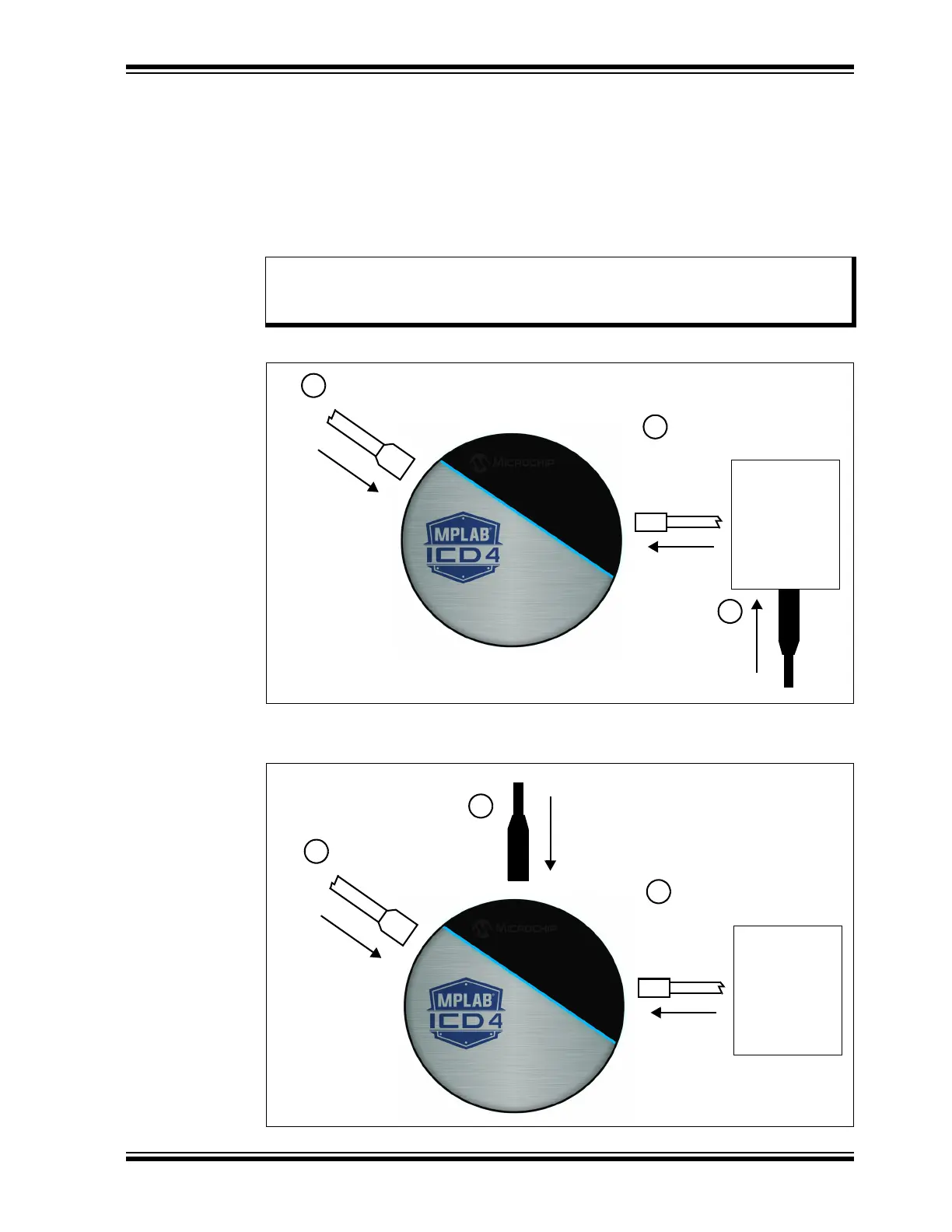
3.6 CONNECTING THE TARGET BOARD
A connection is built in to select the type of communication with the target. See
Section 2.2 “Debugger to Target Communication” for more details and a diagram.
1. Connect the Mini-B USB cable between the debugger and the computer, if not
already connected.
2. Attach the communication cable(s) between debugger and target.
3. Connect power to target or debugger.
FIGURE 3-1: POWERING TARGET DIRECTLY
FIGURE 3-2: POWERING TARGET THROUGH DEBUGGER
Note: In MPLAB X IDE, you can select the source from which to power the target.
In order to power the target from the MPLAB ICD 4 debugger, the power
supply must be connected to the debugger.
Mini-B USB
3
From Power Supply*
Target
Board
1
From Computer
Communications Cable
From Target
2
*Optionally, the Microchip power supply (AC002014)
From Power Supply
3
Mini-B USB
Targ e t
Board
1
From Computer
Communications Cable
From Target
2