About the Debugger
2017 Microchip Technology Inc. DS50002596A-page 15
1.4 MPLAB ICD 4 IN-CIRCUIT DEBUGGER COMPONENTS
The components of the MPLAB ICD 4 In-Circuit Debugger system are:
• A puck-shaped MPLAB ICD 4 unit housed in a durable, black case with a brushed
aluminum top which is accented with an LED indicator bar, and a Mini-B USB
connector, an RJ-45 connector, and a power connector
• A Mini-B USB cable to provide communication between the debugger and a
computer, and to provide power from the computer to the debugger
• A 6-inch modular cable (6-pin RJ-11 type) to connect the MPLAB ICD 4 unit to a
header module or target board
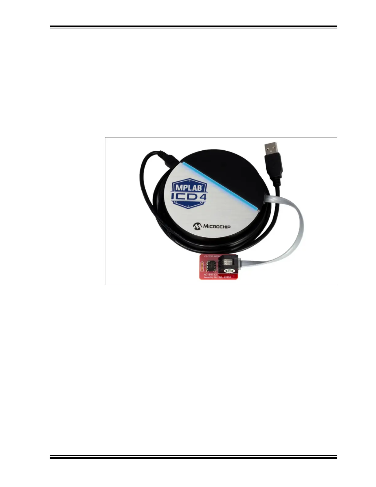
• An ICD Test Interface Module (AC164113) to self-test the debugger
FIGURE 1-1: BASIC DEBUGGER SYSTEM
Additional hardware and accessories may be ordered separately from Microchip Direct
(http://www.microchipdirect.com):
• Power supply (Part Number AC002014) - to provide up to 1A of power to the
target application
• Transition sockets
• ICD headers
• MPLAB processor extension kits
Mini USB Cable
Indicator
Bar
Modular Cable
to Target Board,
Header or ICD
ICD Test Interface
Board
Test Interface
Board
ICD Test Interface Module
Mini-B USB Cable
Modular Cable